
Carrier-Current Baby-Alert Transmitter Circuit

The baby-alert transmitter circuit utilizes the LM324 quad op-amp as the primary processing unit, which provides the necessary amplification and signal conditioning. The circuit is designed to monitor ambient sound levels through a microphone (MIC1). When sound is detected, the op-amp amplifies the audio signal, which is then used to trigger the two LMC555CM timers.
The LMC555CM timers are configured in astable mode to generate a continuous square wave signal at a frequency of approximately 125 kHz. This frequency is chosen to ensure effective transmission and minimal interference with other devices. The output from the timers can be connected to an RF transmitter or directly to an alarm receiver, depending on the application requirements.
Supporting components in the circuit include resistors and capacitors that set the gain of the op-amp and determine the timing characteristics of the 555 timers. Proper selection of these components is essential to ensure reliable operation and optimal performance of the transmitter.
Overall, this baby-alert transmitter circuit serves as an efficient solution for monitoring sound levels in environments such as nurseries, providing a means to alert caregivers when a baby is in distress or making noise. The combination of the LM324 op-amp and LMC555CM timers allows for a compact and effective design that can be integrated into various alarm systems. The baby-alert transmitter is built around an LM324 quad op amp (Ul), two LMC555CM CMOS oscillator/timers (U2 and U3), and a few support components. The transmitter sends a signal on receipt of a sound at MIC1. It has a frequency of around 125 kHz and can be used to trigger an alarm receiver.
Related Circuits

This circuit provides protection for telephones, EPABX systems, telephone modems, and similar devices against lightning discharges and line voltage spikes. It incorporates a safety capacitor and gas discharge components. The circuit employs a safety capacitor to filter out high-frequency noise...
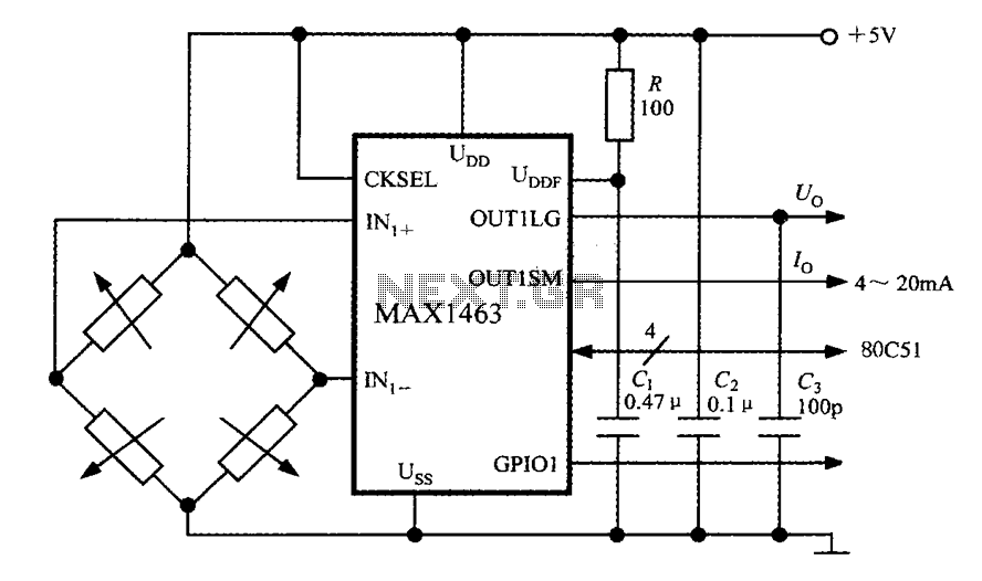
The system consists of a MAX1463 precision pressure detection circuit block diagram. The output voltage from the bridge pressure sensor is connected to the MAX1463 inputs IN1+ and IN1-. Controlled by a CPU, the pressure signal undergoes nonlinear calibration...
This electronic schematic allows for the design of a simple cellular phone detector circuit capable of sensing the presence of an activated mobile phone from a distance of 1.5 meters. The capacitor C3 should have lead lengths of 18...
This circuit utilizes the AD639 universal trigonometric function generator from Analog Devices to transform a triangle waveform, which serves as the fundamental waveform of the VCO, into a low-distortion sine wave. By operating the AD639 in its frequency tripler...
This transmitter utilizes a 741 operational amplifier as a high-gain audio amplifier, which is activated by a microphone. The output of the 741 is connected to Q1, functioning as the driver for an LED. Potentiometer R1 serves as the...
This circuit dials a stored DTMF tone sequence from an EPROM when a control line is taken to 0 V. IC1 is a Schmitt trigger oscillator, operating at approximately 2 Hz. It clocks a 4024 binary counter. The outputs...