
Intelligent sensor signal processor configured MAX1463 precision pressure detection circuit

The MAX1463 precision pressure detection system integrates several critical components to ensure accurate pressure measurement and reliable operation. The bridge pressure sensor serves as the primary transducer, converting pressure into an electrical signal. The output voltage from the sensor is fed into the MAX1463 at the IN1+ and IN1- terminals, where it is conditioned for further processing.
The CPU plays a pivotal role in managing the system. It oversees the nonlinear calibration and temperature compensation processes, which are essential for maintaining measurement accuracy across varying environmental conditions. The A/D converter converts the conditioned analog signal into a digital format, which is then sent to the 80C51 microcontroller via a serial output interface. This microcontroller acts as the central processing unit, executing algorithms stored in flash memory to ensure precise linearization and compensation of the sensor signals.
The digital-to-analog converter (DAC) is responsible for generating an analog output voltage (Uo), which reflects the measured pressure and is displayed on a digital voltmeter. This output facilitates easy monitoring of pressure values in real-time.
In terms of system reliability, the GPI01 pin connected to the fault alarm system is crucial. It serves as a safeguard against potential faults, such as sensor lead disconnections or CPU errors during program execution. In such cases, the system activates a buzzer to alert users of the issue, ensuring prompt attention to any anomalies.
The internal clock oscillator of the MAX1463, set to 4MHz when the CKSEL pin is high, provides a stable timing reference for the CPU and ADC. This synchronization minimizes system noise, enhancing the overall performance and reliability of the pressure detection system. The architecture of this system reflects a careful design aimed at precision, reliability, and user safety in pressure measurement applications.Constituted by a circuit block diagram MAX1463 precision pressure detection system as shown in FIG. Bridge pressure sensor output voltage connected to the MAX1463 IN1 +, IN1- e nd. Under the control of CPU, the pressure signal sequentially through a nonlinear calibration and temperature compensation after A/D conversion from the serial output interface to 80C51 microcontroller; DAC also been converted to an analog output voltage Uo, sent to the digital voltmeter is showing measured pressure value. General-purpose digital I/O interface GPI01 pin is connected to a fault alarm, when overflow sensor lead open or CPU occurs during program execution, you can drive the buzzer alarm.
Linearization and temperature compensation of the sensor signals are stored by a user-defined algorithm done in flash by. CPU according to prescribed procedures to execute instructions stored in flash memory. When CKSEL termination high, MAX1463 selects the internal 4MHz clock oscillator. Since the CPU and operation of the ADC is fully synchronized, thus reducing the system noise.
Related Circuits
Remove the 6 mm screw that secures the lower rear fairing cover. This cover is the black plastic piece to which the spark plug protectors are attached. Only the machine screw should be removed; do not detach the lower...
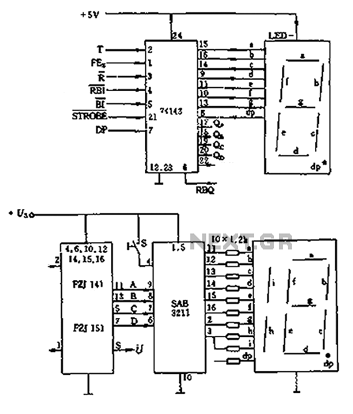
The decimal seven-segment storage decoding drive unit 74HC143 provides a constant output for all segments, each at a voltage of 5V and a current ranging from approximately 15mA to 22mA. The BCD data for the seven-segment decoder can be...
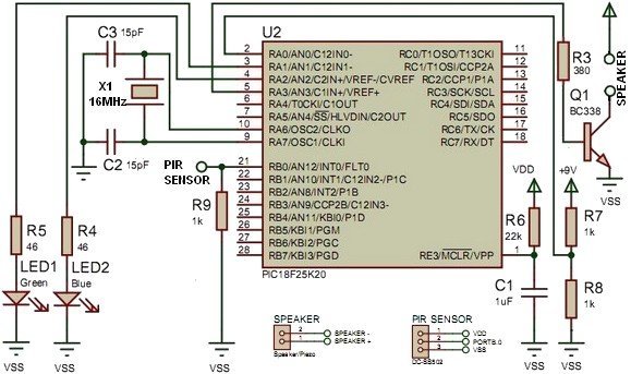
This project utilizes the PIC18F25K20 microcontroller to detect changes in a sensor's state and emit sound from a speaker or piezo buzzer. The microcontroller also monitors the battery voltage during startup. The algorithm is straightforward, employing an interrupt-on-change mechanism...
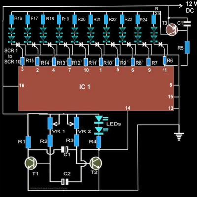
The article explains a straightforward method for creating an incremental LED bar graph using the IC 4017, which has specifications that may not fully align with current requirements. It discusses how to modify the IC for these operations. The...
This audio processor circuit features the SSM2045 integrated circuit (IC), designed specifically for electronic music applications, along with the 741 operational amplifier (op-amp) IC. The circuit is configured as a low-pass filter with a DC voltage control for gain....

The LT6552 is a video difference amplifier optimized for low voltage single supply operation. The LT6552 features a 75MHz 3dB bandwidth, a 600V/µs slew rate, and ±70mA output current, making it ideal for driving cables directly. This circuit maps...