
Cashbox or Locker Alarm

The locker alarm circuit utilizes a reed switch that acts as a magnetic sensor. When the locker or cashbox door is closed, a magnet positioned near the reed switch keeps it in a closed state, allowing the circuit to remain inactive. In the event of unauthorized access, if the door is opened and the magnet moves away from the reed switch, the switch will open, triggering the alarm.
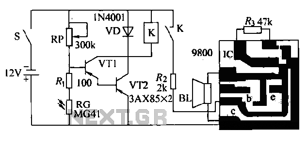
The heart of the circuit is an electromagnetic relay, which is used to drive the alarm system. The relay is connected in such a way that when the reed switch opens, it energizes the relay coil, closing the relay contacts. This action can activate various alarm systems, such as a siren or a flashing light, providing a clear indication of unauthorized access.
Powering this circuit with a 12V DC supply ensures that it can operate efficiently while providing adequate power to the relay and alarm components. It is crucial to select a relay that can handle the load of the intended alarm system to prevent damage to the components.
For enhanced functionality, additional features can be integrated into the circuit, such as a delay timer to prevent false alarms or a secondary notification system that alerts the owner via a mobile device or a landline. Proper enclosure of the circuit is essential to protect it from environmental factors and tampering, ensuring reliable operation in various conditions.
Overall, the locker alarm circuit is a practical solution for protecting valuable items from theft, combining simplicity with effectiveness in design.The locker alarm circuit or cashbox watcher can be used to protect a cashbox/locker from unauthorised access. This tried and tested design forms a fool-proof,remotely operated alarm/electromagnetic relay driver that receives its control signal from a standard reed switch.
The circuit works off a 12V dc power supply.After construction, enclose the whole circu.. 🔗 External reference
Related Circuits

Children often go missing, causing immense suffering and economic losses for families. This situation also presents opportunities for unscrupulous child traffickers to exploit. To address this issue, a radio alarm system has been designed, which consists of a transmitter...

The following circuit illustrates a fire alarm circuit diagram utilizing the NE555 integrated circuit (IC). Features include functioning as a heat sensor and incorporating a 10 kilo-ohm resistor. The fire alarm circuit based on the NE555 IC is designed to...

The TL081 is utilized as a comparator within a Wheatstone bridge circuit. When the resistance of the CDS cell decreases due to light exposure, the output from IC2 prompts the low-frequency oscillators (a) and (b) to produce a 10-Hz...

This circuit automatically activates a night lamp when the bedroom light is turned off. The lamp stays illuminated until the light sensor detects daylight in the morning. A super-bright white LED is utilized as the night lamp, providing bright...

The tone generated by a 555 oscillator can be activated by heat or light, which causes Q1 to conduct transistor Q2 (TIP 3055). Q2 (TIP 3055) functions as an audio amplifier and speaker driver. The circuit utilizes a 555 timer...
The circuit presented is a second-generation flame alarm for natural gas stoves. After the gas stove is ignited and normal combustion occurs, the power switch S is closed. The photoresistor RG, influenced by the light from the flame, has...