
Cat And Dog Repellent Timer

The Cat and Dog Repellent Timer Circuit is designed to emit high-frequency ultrasonic sound waves that are unpleasant to cats and dogs, effectively deterring them from entering certain areas. The core of this circuit utilizes a 555 timer IC, which operates in astable mode, generating a continuous square wave output. This output is fed into an ultrasonic transmitter, which converts the electrical signal into sound waves.
The circuit typically consists of several key components: a 555 timer IC, resistors, capacitors, a transistor for amplifying the signal, and the ultrasonic transducer itself. The resistors and capacitors connected to the 555 timer determine the frequency of the output signal, which is generally set between 20 kHz and 25 kHz, a range that is inaudible to humans but can be heard by animals.
The ultrasonic transducer is responsible for converting the electrical signal from the timer into ultrasonic sound waves. The output from the 555 timer is usually insufficient to drive the transducer directly, so a transistor is employed to amplify the signal. This amplification ensures that the ultrasonic waves produced are strong enough to be effective in repelling animals.
The circuit can be powered by a standard DC power supply, and it may include features such as an adjustable timer to control how long the ultrasonic sound is emitted. Additionally, it can be designed to operate intermittently, thereby conserving power and prolonging the life of the device.
This circuit is particularly useful for homeowners looking to protect their gardens or outdoor spaces from unwanted animal intrusions without causing harm to the animals. The simplicity of the design allows for easy assembly and customization, making it accessible for hobbyists and professionals alike.The following circuit shows about Cat And Dog Repellent Timer Circuit Diagram. Features: high output ultrasonic transmitter, uses a standard 555 .. 🔗 External reference
Related Circuits
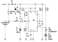
The sections available in this datasheet cover general design considerations for the 555 timer, frequently asked application questions (FAQ), design formulas, and examples of innovative applications. Examples of applications include a Missing Pulse Detector, Pulse Width Modulation (PWM), Tone...
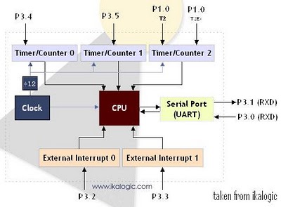
The diagram below illustrates a simplified representation of the main peripherals present in the 89S52 microcontroller, which is part of the 8052/8051 family. The 89S52 includes three Timers/Counters. The term "Timer/Counter" is applicable because this unit can function either...
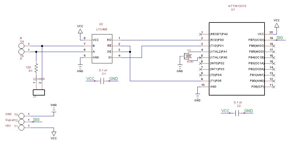
This is a 16x2 switcher, providing ample room for expansion. While the cameras are satisfactory, the primary requirement was the capability to pan and tilt the selected cameras to adjust the view as needed. Extensive research revealed that most...
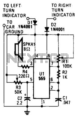
This circuit is designed to assist individuals with hearing impairments by generating a tone each time a dashboard turn indicator is activated. The frequency of the tone decreases for the duration that the indicator remains lit. The circuit operates by...

This circuit utilizes standard components to indicate the fuse status of mains-powered equipment while ensuring electrical isolation from the mains supply. A standard miniature low-power mains transformer (for example, with an output of approximately 6 V at 1.5 VA)...
It is well known that many animals are particularly sensitive to high-frequency sounds that humans cannot hear. Many commercial pest repellers based on this principle are available, most of them operating in the range of 30 to 50 kHz....