
Automotive Audible-Turn Indicator Circuit

The circuit operates by monitoring the state of the turn indicator lights, which are typically controlled by a relay or a direct connection to the vehicle's lighting system. When the turn indicator is activated, a signal is sent to the tone generator circuit. This circuit can consist of a simple oscillator, such as a 555 timer configured in astable mode, which produces a square wave output.
The frequency of the output tone can be controlled by varying the resistor and capacitor values in the timing circuit. To achieve the desired effect of a decreasing frequency, a feedback mechanism can be implemented. This can be accomplished by integrating a capacitor that gradually discharges while the indicator is lit, effectively lowering the frequency over time.
Additionally, a transistor can be used to amplify the tone output, ensuring it is audible even in noisy environments. A small speaker or piezo buzzer can be connected to the output of the transistor, providing a clear sound that alerts the user when the turn indicator is active.
Power for the circuit can be drawn from the vehicle's battery, with appropriate voltage regulation to ensure safe operation of the electronic components. A diode may be included to protect against reverse polarity connections.
This circuit not only enhances safety by providing auditory feedback for turn signals but also caters specifically to the needs of those with hearing impairments, allowing for a more inclusive driving experience. This little circuit should be useful to the hearing impaired. It produces a tone each time a dashboard turn indicator lights. The tone drops in frequency for as long asthe indicator is lit.
Related Circuits
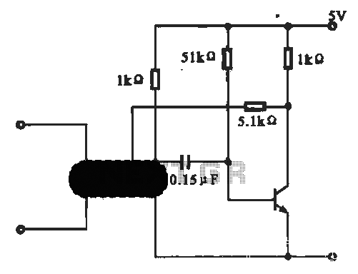
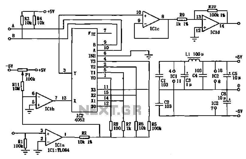
This circuit illustrates an oscillator that is controlled by an optocoupler, utilizing photoelectric coupling to drive a transistor. The oscillator circuit described operates by employing an optocoupler to provide electrical isolation between its input and output stages while allowing control...
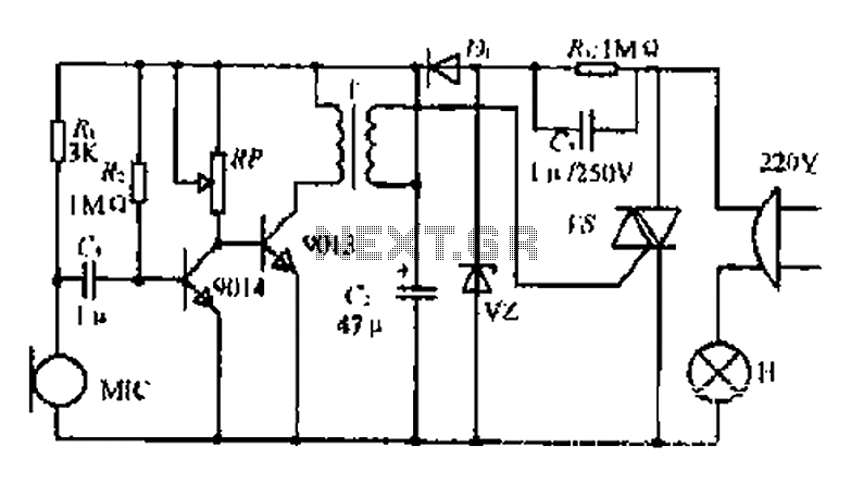
22W by Ct and R, RC Buck, rectified by n. c, filtering. vz 3V DC regulated output power, before U, V2 and MIC power supply. When the audio signal reaches the beam, the microphone MI converts acoustic energy into...
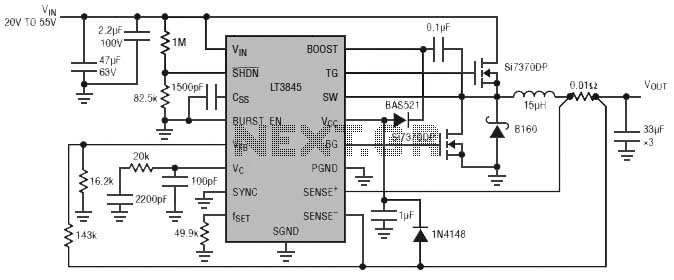
Burst Mode operation maintains high efficiency at light loads by reducing IC quiescent current to 120 µA. Light load efficiency is also improved with the reverse inductor current inhibit function, which supports discontinuous operation. Additional features include an adjustable...
Typical segment display LEDs consume around 25 mA for each segment and should be limited to this current with resistors. For a six-digit display to be current limited, at least 42 series resistors are needed. The brightness of the...
The PGA103 is designed with a wide input voltage range. It utilizes a voltage divider circuit consisting of a 11.3kΩ resistor and a 102kΩ resistor, achieving a division ratio of approximately 1/10. For instance, when the input voltage is...
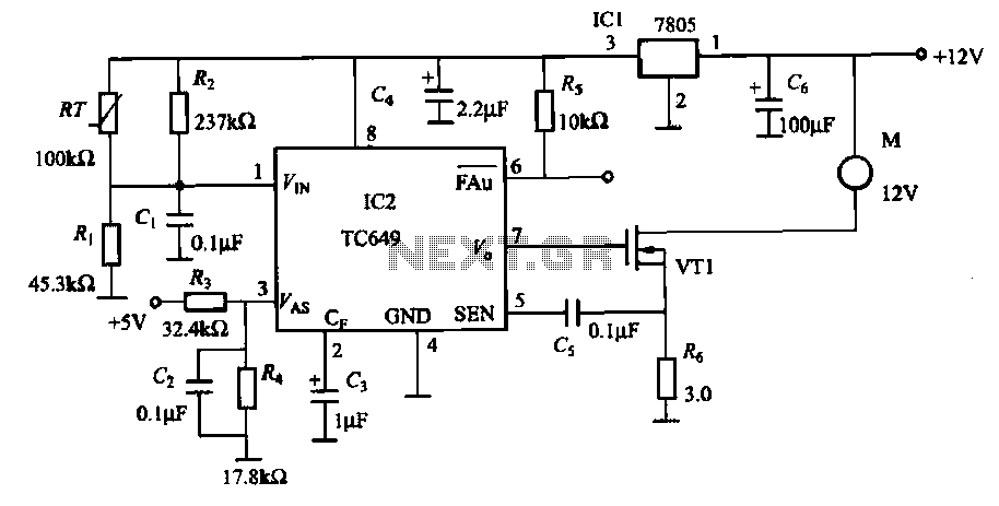
A motor is a heating device that can overheat, often due to accidents or overloads caused by excessive coil winding temperatures. The TC649 motor overheating protection and drive circuit, depicted in FIG. 1-9, utilizes an NTC thermistor (RT) positioned...