
CB 27MHz Transmitter Circuit

The 27 MHz NBFM transmitter circuit operates by employing the Motorola MC2833, a versatile chip that simplifies the design of FM transmitters. The core functionality revolves around narrow band frequency modulation, which allows for efficient use of bandwidth while maintaining audio fidelity. The transmitter is configured to operate within the 27 MHz band, commonly used for various communication applications, including hobbyist radio and short-range communications.
Key components of this circuit include the microphone preamplifier, where the potentiometer P1 plays a critical role in adjusting the gain to ensure that the audio signal is adequately amplified before modulation. The second potentiometer, P2, is essential for controlling the frequency deviation, which directly influences the modulation depth and audio quality transmitted.
Capacitors C9, C10, and C18 are crucial for tuning the circuit to achieve maximum output power. These components help stabilize the oscillator and filter the signal, ensuring that the transmitter operates efficiently under varying load conditions. The use of an artificial 50-ohm load during the tuning process ensures that the output power can be accurately measured, leading to optimal performance.
After adjusting the capacitors for maximum output, the circuit should be monitored using an NBFM receiver. This step is vital for ensuring that the transmitted audio signal is clear and free from distortion. Fine-tuning P1 and P2 allows for adjustments to be made in real-time, ensuring that the modulation is at its best for the intended application.
Overall, this 27 MHz NBFM transmitter circuit exemplifies a straightforward yet effective design for FM transmission, leveraging the capabilities of the MC2833 chip to deliver reliable performance in various communication scenarios.NBFM or Narrow Band Frequncy Modulation is used in this 27 MHz transmitter circuit schematic. This circuit is an application by Motorola MC2833 VHF transmitter with FM modulation and narrow band in a single chip. P1 is used to adjust microphone amplification and P2 to adjust the deviation. Remember that this 27MHz fm transmitter use NBFM withmaximum 5KHz deviation, this mean you have to use an nbfm receiver to obtain enough audio level. The transmitter is easy to adjust: trim C9, C9 and C18 for maximum output power on a artificial 50 © load. Then listen on a 27MHz radio receiver and adjust P1 and P2 untill you obtain the best modulation. 🔗 External reference
Related Circuits
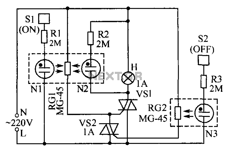
The circuit operates based on the principle that neon tubes N1, N2, and the photosensitive resistor RG1 form an optocoupler. When a finger touches the metal sheet S1, N1 lights up, causing RG1's resistance to decrease. This reduction allows...
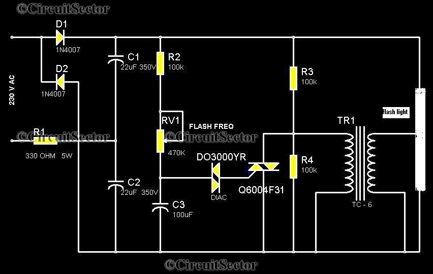
This circuit is a strobe light that allows for adjustable flashing rates. It utilizes a flash tube commonly found in cameras. In standard cameras, the flash may take ten to twenty seconds to recharge. However, this circuit enables the...
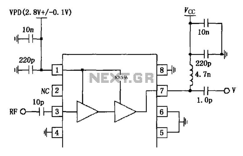
The circuit is constituted by the RF2324 1880MHz internal amplifier collector bias application. A radio frequency (RF) signal enters through input pin 3 and is processed by a preamplifier. The final stage power amplifier output is amplified by 7...

Basic features include an internal 512k-bit EEPROM, allowing for continuous recording and playback at any time, with long-term retention of voice data after power loss. The voice recording time is 20 seconds, and it supports segmented recording and playback....
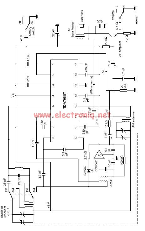
The TDA7088 features a frequency-locked-loop (FLL) system with an Intermediate Frequency (IF) of approximately 70 kHz. This circuit can be powered using a 3-volt battery cell or a regulated power supply. The TDA7088 is a highly integrated FM radio receiver...
This is a simple mains power failure alarm circuit that activates an alarm when the mains supply is lost. Unlike many similar circuits, this design does not require a backup power source, such as a battery, to operate the...