
Cell Phone Shield with Charger

The cell phone shield circuit is designed to enhance security for mobile devices by integrating an astable multivibrator configuration that continuously oscillates, generating a periodic output signal. The use of the NE555 timer IC in this configuration allows for reliable operation without the need for an external timing capacitor, relying instead on inherent stray capacitance within the circuit. The monostable multivibrator, on the other hand, serves to trigger an alarm condition that activates when the mobile device is tampered with or removed from its designated area.
The protective shield, constructed from a copper-clad board, provides a physical barrier while also serving as a ground plane to minimize electromagnetic interference (EMI). The chirping sound produced acts as an audible deterrent against theft, alerting nearby individuals to unauthorized attempts to access the mobile device. The astable multivibrator's output can be connected to a small speaker or buzzer, effectively amplifying the sound produced.
In addition to its protective features, the circuit is designed to function as a solar-powered battery charger. The LM78xx voltage regulator ensures that the output voltage remains stable, allowing for safe charging of mobile devices. The circuit's simplicity and cost-effectiveness make it an appealing option for individuals seeking an affordable solution to mobile charging needs.
Furthermore, the electronic siren circuit, utilizing the NE555 timer in an astable configuration, demonstrates versatility in sound generation. By adjusting the frequency through the resistor connected to pin 5, the user can tailor the output sound to fit specific requirements, whether for alarm systems or other applications needing an audible alert. The integration of these components into a cohesive design illustrates the potential for creating multifunctional electronic devices that enhance both security and utility in everyday applications.The cell phone shield circuit uses two NE555 timer ICs: One as being a very simple astable multivibrator (IC2) and then the 2nd as being a monostable multivibrator (IC3). The astable multivibrator has timing resistors R1 and R2 but no timing capacitor since it operates with stray capacitance.
Its pins 6 and 2 are directly joined to a safeguarding shield built up of 10cmG—10cm copper-clad board. This is the cell phone shield circuit which can be used as mobile charger. Give protection to your cell phone from unexpected use or theft working with this easy circuit. It is able to produce a loud chirping sound when someone tries to take away the mobile handset. The added function is that the circuit. A multivibrator is an electronic circuit used to implement a variety of simple two-state systems such as light emitting diodes, timers and flip-flops. The monostable multivibrator will create a condition: in which one of the states is stable, but the other is not ”the circuit will flip into the unstable state for a determined period, but.
This is the schematic diagram of solar powered mobile phone battery charger. The circuit is designed to charge the battery from a source with a lower voltage. Do not use it to charge the battery with the same or lower voltage than the voltage which is generated by the solar panel. For proper operation of. The following diagram is a simple mobile phone battery charger circuit. The design is simple, easy to build and inexpensive. It use LM78xx regulator to make regulated and stable output voltage. Mobile phone chargers offered in the marketplace are quite expensive. The circuit shown right here shows up as a low-cost option to charge cell. Here the circuit diagram of electronic siren based NE555. This circuit produces a sound like factory siren. It applies a 555 timer IC which is utilized as an astable multivibrator of a center frequency of about 300Hz.
The frequency is controlled by the pin 5 of the IC. When the power supply is switched ON, . This easy electronic buzzer circuit built based on timer works for gaining the frequency. The IC timer NE 555 used as astable multivibrator operating at about 1kHz and produces a sound when switched on. The sound frequency can be adjusted by varying the 10K resistor. You may change the 10K resistor with variable resistor. 🔗 External reference
Related Circuits
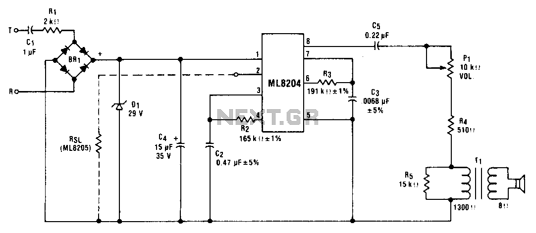
This circuit utilizes ML8204/ML8205 devices. The components illustrated result in an output frequency that oscillates between 512 Hz (fin) and 640 Hz (fb) at a modulation rate of 10 Hz (t). The circuit employing ML8204/ML8205 devices is designed for frequency...
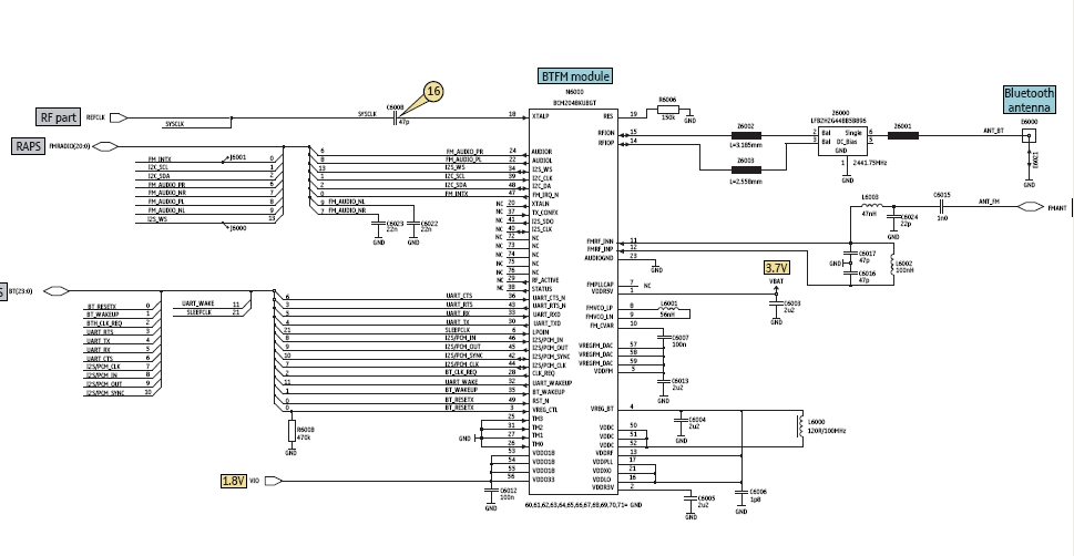
Bluetooth is an open wireless technology standard for exchanging data over short distances between fixed and mobile devices, utilizing short wavelength radio transmissions to create personal area networks (PANs) with high security. The Bluetooth baseband protocol combines circuit and...
The M7 capsule features a center-terminated, dual-diaphragm design and supports three polar patterns. A switch on the power supply allows for the selection of Cardioid, Figure-of-8, or Omnidirectional patterns. The amplifier circuit is reminiscent of Gefell's historical models, the...
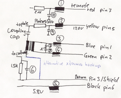
The interval between rings can be adjusted by changing the value of the 1 Meg resistor. A 70 volt, 30 Hz ringing voltage is generated from the 120 volt side of a small 12.6 VAC power transformer (Radio Shack...
A long time ago, when telephones were simple and reliable from an electrical standpoint, telecom operators installed surge protection on all telephone lines at risk from storms. Paradoxically, as modern technology has led to the use of delicate and...
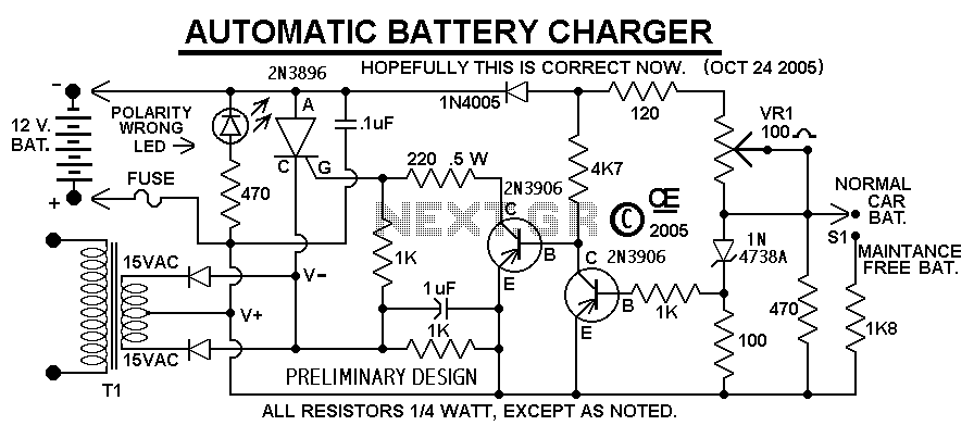
This Charger Can't be used as a Power Supply, Without having a battery in place. The Battery MUST be Connected to get power out. Note: This Charger Features a Reverse polarity Indicator. Instructions: Before plugging this charger into the...