
bluetooth circuit in mobile phones

The Bluetooth circuit operates by utilizing a series of interconnected components that facilitate wireless communication. At the core of the system is the Bluetooth transceiver module, which integrates both the transmitter and receiver functionalities in a compact IC. This module requires a stable power supply, typically sourced from the main battery of the mobile device, ensuring that it operates efficiently during data transmission and reception.
The data flow within the Bluetooth circuit begins at the Bluetooth antenna, which captures incoming RF signals and transmits outgoing signals. The RF transceiver processes these signals, converting them to a digital format that can be handled by the application processor. The application processor is responsible for executing the software that manages Bluetooth connections, handles data packets, and interfaces with other applications on the mobile device.
The RF clock signal, which synchronizes the operations of the Bluetooth module, is critical for maintaining the timing of data transmissions. It ensures that packets are sent and received at the correct intervals, thereby minimizing errors and maximizing the reliability of the connection. Troubleshooting Bluetooth issues often begins with verifying the integrity of the power supply and the RF clock signal, as these are fundamental to the proper functioning of the entire system.
The circuit schematic diagram serves as a valuable tool for technicians, providing a visual representation of how each component is connected. This diagram allows for easy identification of critical points within the circuit, such as the voltage supply and RF clock, which are essential for effective troubleshooting. By following the schematic, technicians can trace signals through the circuit, identify faulty components, and implement repairs or replacements as needed.
In summary, the Bluetooth circuit in mobile phones is a complex integration of various components that work together to enable wireless communication. Understanding the layout and operation of these components is crucial for effective troubleshooting and repair, making the circuit schematic an indispensable resource for technicians in the field.Bluetooth is an open wireless device technology standard for exchanging data over short distances from fixed and mobile devices(using short wavelength radio transmissions), creating personal area networks (PANs) with high levels of security. The Bluetooth baseband protocol is a combination of circuit and packet switching. Slots can be reserved for synchronous packets. Each packet is transmitted in a different hop frequency. A packet nominally covers a single slot, but can be extended to cover up to five slots. Bluetooth can support an asynchronous data channel, up to three simultaneous synchronous voice channels, or a channel, which simultaneously supports asynchronous data and synchronous voice. Since we are talking about mobile phones here, it is much more really great to know how really bluetooth circuit works on cell phones circuit Isn`t it nice to know, so that we can easily managed how to fix it since it is our main reason in this tutorials by learning how to repair damaged cell phone devices.
In mobile phones Bluetooth problems also occurs when the bluetooth circuit is damaged, Some new cell phone techie find it hard to fix bluetooth for not knowing how the circuit works. Okay, lets tackle it for a while in just very simple explanation so that all of those without any background in electronics might can catch up too, and then we can use it in our everyday job on GSM field.
Figure the bluetooth circuit block diagram below for it shows how the Bluetooth Circuit works according to each corresponding parts or components that is being connected to it. The bluetooth transceiver module is packed into chip or IC (integrated circuit), this chip needs a certain power supply to make it work.
All the data that has been transmit (send) and receive from the bluetooth antenna and bluetooth RF (radio frequency) transceiver is feeds in for receiving and feeds out when sending to the application processor (cpu IC). There is an RF clock which comes from the RF circuit section is also feeds into it, that certain RF - Radio frequency is also needed by the bluetooth module to make it fully functional.
Since all those certain parts on bluetooth circuit were packed only into chips. A way to truly understand how does the circuit connect with each other from each certain components is by reading the circuit schematic diagram to locate this certain components parts on the main PCB board so that we can be able to check, trace and fix when a bluetooh failure happens. here`s an example of the bluetooth schematic diagram and figure out how each components connect with other.
In this method you can easily identify where that certain parts connected from one another. See here: You`ll notice that all of the bluetooth components is mounted in one section and near to each other. Some important spots is being labeled for quick troubleshooting guide. Like this picture below, the voltage supply and the RF clock are being labeled for quick check up and test procedures.
The key reason with this is that when it comes fixing bluetooth problem issues is to check the supply voltage and the RF clock signal first before trying to check, test, replace any other corresponding components being connected within the whole bluetooth circuit. 🔗 External reference
Related Circuits
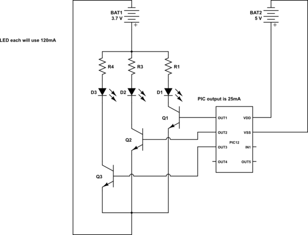
This is a conceptual schema utilizing a PIC12 microcontroller to control the blinking of three LEDs, each exhibiting different blinking patterns. There are several questions that need to be addressed. The circuit design involves a PIC12 microcontroller, which is a...
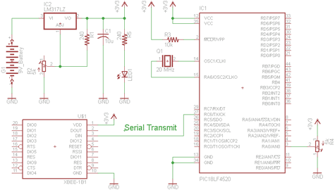
There are two schematics to examine for constructing a transmitter/receiver system. The first schematic is the transmitter, featuring a variable trimpot connected to RA0. The trimpot's value will be transmitted from the Tx pin of the PIC to the...
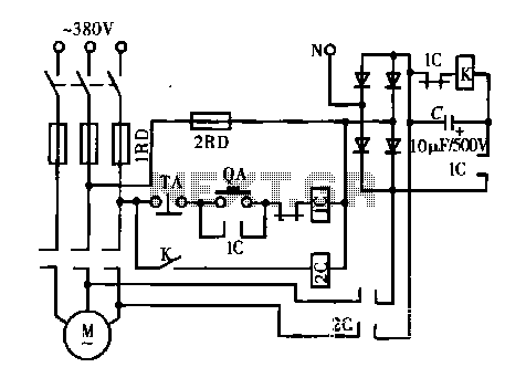
A DC motor is depicted in a dynamic braking circuit. When the stop button (SB2) is pressed, the contactor (KM1) is deactivated, causing its movable contact to disconnect, which interrupts the electrical voltage. Additionally, relay (KV) is activated, closing...
The cooling is not only a PC using a small fan with an electronic commutator. A special feature of these fans is that their removal is less dependent on the load. Indicators monitoring the DC component of current may...
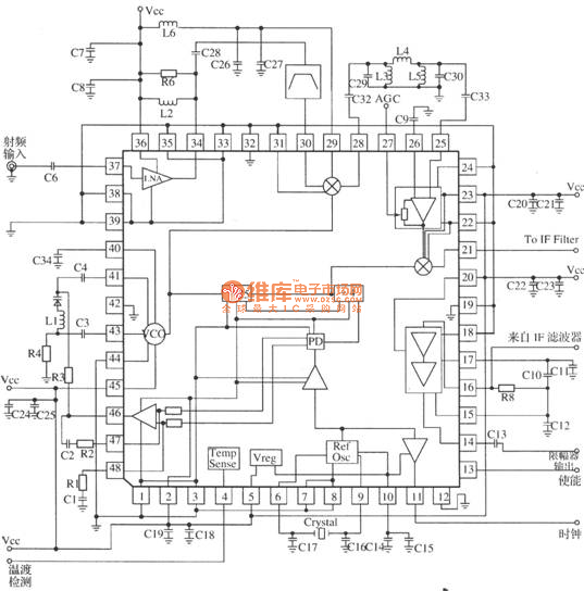
MRFICl505R2 is a 1.575GHz GPS downconverter chip. It integrates a mixer, VCO, PLL, crystal oscillator, A/D converter, loop filter, and other circuits. The MRFICl505R2 IF output frequency is 4.1MHz, with a typical conversion gain of 105dB, an operating voltage...
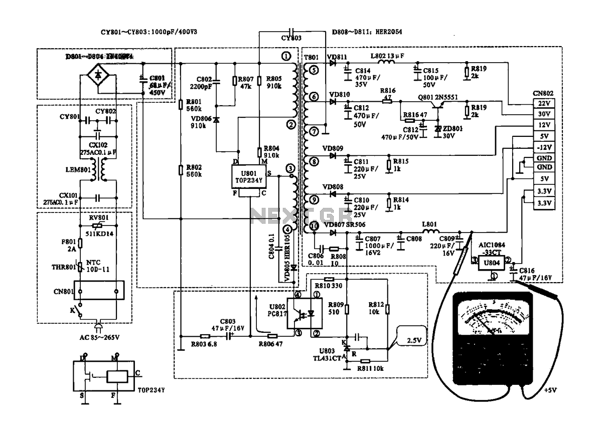
The Coship CDVB3188V receiver features a switching power supply circuit similar to the CDVB3188C model. The circuit includes several key components: an AC input circuit, an anti-jamming filter circuit, a complete flow filter circuit, and a switching oscillation circuit....