
cellphone operated land rover connection to mobile phone problematic

The circuit under discussion involves the integration of a DTMF decoder (MT8870) with a microcontroller (AT89S52) and an LED display. The MT8870 is designed to decode Dual-Tone Multi-Frequency (DTMF) signals, which are commonly used in telephone systems. When a key is pressed on the keypad of the Nokia 2300, the corresponding DTMF tone is generated and sent to the MT8870. The MT8870 processes this signal and outputs a binary representation of the key pressed.
In this setup, the AT89S52 microcontroller is programmed to read the output from the MT8870. The microcontroller’s port 0 is connected to the output pins of the MT8870, while port 1 is connected to an LED board that visually displays the binary output. The expected behavior is that when a key is pressed, the MT8870 will output a binary value corresponding to that key, which will then be transferred to the LED board for visualization.
The issue arises when the output remains at 0000 regardless of key presses. This suggests that either the MT8870 is not receiving the DTMF signals correctly, or there is a problem in the communication between the MT8870 and the microcontroller. To troubleshoot, it is advisable to first isolate the MT8870 by disconnecting the microcontroller and using a multimeter to check the output of the MT8870. This test will confirm whether the DTMF decoder is functioning correctly.
If the MT8870 is operational, attention should then be directed to the microcontroller's programming and connections. Ensuring that the program correctly reads the output from the MT8870 and that the connections between the microcontroller and the decoder are secure is essential. The suggested changes to resistors and capacitors may also influence the performance of the circuit, particularly in terms of signal conditioning and stability.
In summary, the successful operation of this project hinges on the proper functioning of both the MT8870 and the AT89S52 microcontroller, along with appropriate connections and signal processing. Each component should be tested independently to isolate and resolve any issues present in the circuit.Using Nokia 2300 for my project and the original earphones that came with it. They work properly when listening to radio, or talking to someone over the phone. However, the MT8870 IC does not give output when I connect it to my AT89S52 microcontroller. I have written a simple program to transfer everything from port 0 to port 1 (in which an LED board is connected) - so that the corresponding output of the MT8870 (binary) will be shown on the LED board. But it continuously shows 0000, even on pressing keys. I would be better if you check just the MT8870 receiver part first, remove your microcontroller and see the output of DTMF decoder using multimeter. this will ensure that a part of your circuit is working fine. then you can check controller side if things are going wrong. Thank you everyone for your efforts! I went to my instructor and he suggested a few resistors and capacitor changes, am going to try that and hope it will work!
🔗 External reference
Related Circuits
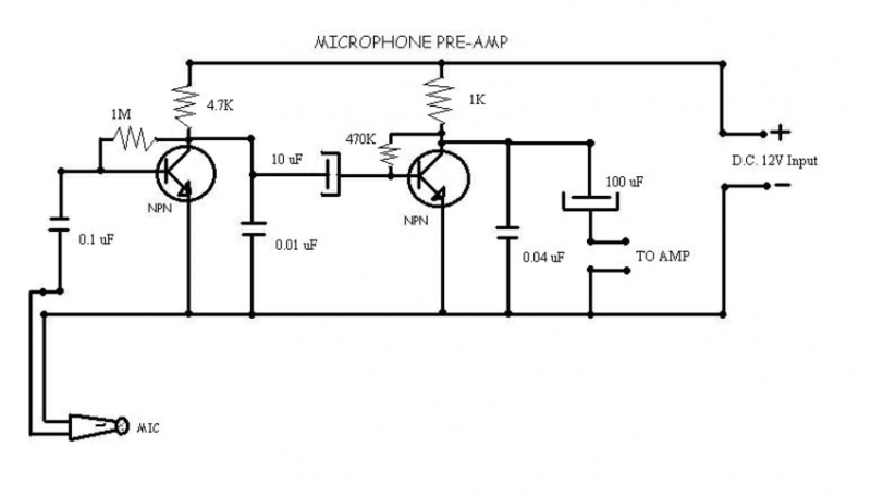
This circuit is used to give out a microphone preamp to an amplifier which will power the signal. The NPN transistors used are ECG123A. This circuit is also an older model to the one that now uses IC's,...

The AC ringing voltage, typically ranging from 40 to 90 V at 26 Hz, is rectified by U1, the tone-ringer integrated circuit (IC), which is utilized to drive the internal tone-generator circuitry. This tone-generator IC comprises a relaxation oscillator...
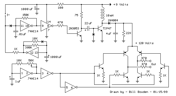
The telephone ring generator illustrated below produces the necessary high voltage using a simple switching mode power supply (SMPS) that incorporates a CMOS Schmitt Trigger square wave oscillator, a 10 mH inductor, a high voltage switching transistor (such as...

The device is a DC switch that remains normally on due to the forward biasing of Q1 through resistor R3. Q1 clamps Q2 into a forward state by biasing its complementary transistor well into saturation via resistor R4. The...
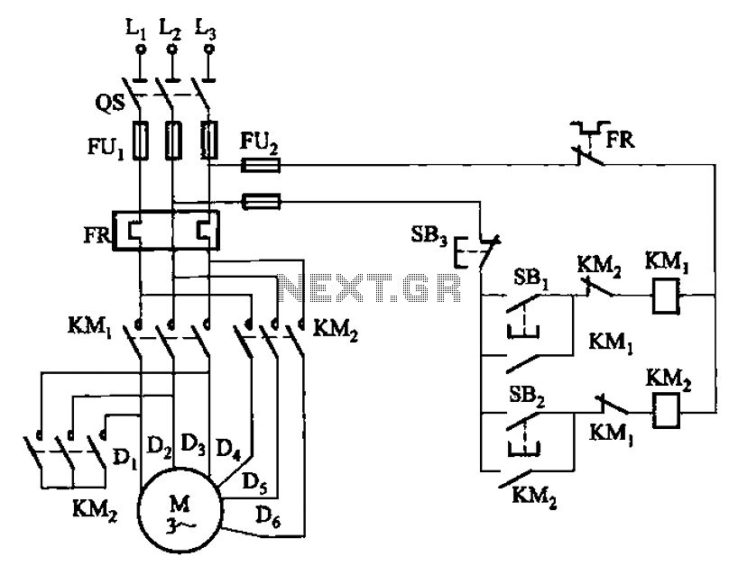
The circuit illustrated in Figure 3-97 features two contacts and is designed specifically for a 2kW dual-speed motor. In this configuration, SB1 is utilized for low-speed operation, while SB2 serves as the high-speed run button. The circuit operates by allowing...

A compilation of dial phone numbers, including 15 commonly used libraries and the dialed number, is stored in standard CMOS RAM. A single-button keypad facilitates the input of a phone number, which can be dialed directly or stored in...