
2Y- connection two-speed motor contactor control circuit 2

The circuit operates by allowing the user to select between two distinct speed settings for the motor, enabling efficient performance based on the application's requirements. The low-speed setting, activated by the SB1 button, is typically used for tasks that require more torque and less speed, making it suitable for applications such as starting heavy loads or operating machinery that benefits from controlled acceleration. Conversely, the high-speed setting, engaged through the SB2 button, facilitates faster operation, ideal for tasks that require quick movement or reduced processing time.
The two contacts in the circuit serve as switches that control the flow of current to the motor, effectively changing its operational speed. The design ensures that only one speed can be active at a time, preventing potential damage to the motor or the circuit itself. This is often achieved through a simple relay or contactor mechanism that engages the appropriate speed setting based on the button pressed.
In summary, the circuit in Figure 3-97 represents a straightforward yet effective solution for controlling a dual-speed motor, optimizing its performance for varying operational demands. The clear distinction between low and high-speed operation, facilitated by the respective buttons, enhances usability and operational flexibility. Circuit shown in Figure 3-97. The circuit only two contacts, the circuit is simple, but only applies to the following 2kW dual speed motor. Figure, SBi is running at low speed button, SBz high-speed run button.
Related Circuits
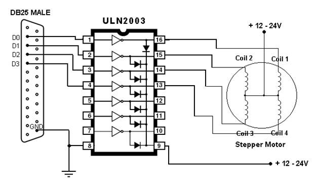
This article outlines the process of connecting a stepper motor to a computer's parallel port and writing code to control it using the scroll wheel of a mouse. For those unfamiliar with stepper motors, this project offers an engaging...
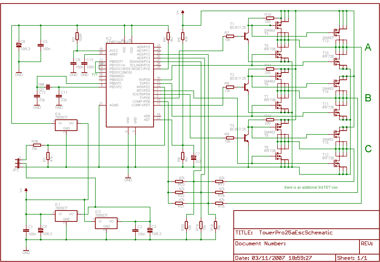
Is it feasible to eliminate the Electronic Speed Controllers (ESCs) from a multicopter configuration and substitute them with a single circuit board to control all the motors? The current setup consists of eight motors, each requiring an individual ESC,...
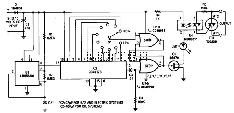
A timer (LM555CN) and decode counter are utilized to generate duty cycles ranging from 10% to 100% for controlling the operational time of a heating system. V2 operates as a decode counter that can be adjusted for duty cycles...
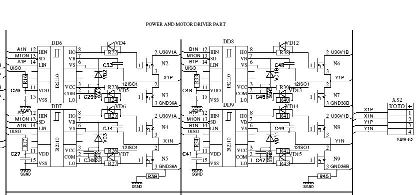
The primary application area for brushless direct current motors (BLDC) is in positioning systems. Brushless Direct Current (BLDC) motors are widely utilized in various positioning applications due to their high efficiency, reliability, and precise control capabilities. These motors operate without...

This is a simple design schematic for a phase control circuit that regulates the power delivered to an AC load. The phase control circuit modifies the AC waveform, allowing for variations such as full cycle, half cycle, zero cycle,...
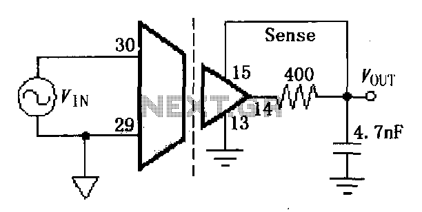
The ISO107 ripple reduction circuit includes an RC high-pass filter at the output to filter the output voltage ripple without impacting the DC characteristics. This configuration allows for a reduction of the 800kHz ripple voltage to less than 3mVp-p. The...