
Cellular phone detector circuit schematic

The cellular phone detector circuit is designed to identify the presence of a cellular phone within a specified range. This circuit utilizes basic electronic components, making it accessible for hobbyists and engineers alike. The primary components typically include a radio frequency (RF) receiver, an operational amplifier, and a series of passive components such as resistors and capacitors.
The RF receiver is crucial for detecting the signals emitted by cellular phones. It is tuned to the specific frequency bands used by mobile phones, allowing it to pick up incoming signals effectively. The output of the RF receiver is then fed into an operational amplifier, which amplifies the signal for further processing.
Additional components, such as diodes, may be included to rectify the output signal, converting it from AC to DC. A visual indicator, such as an LED, can be incorporated into the circuit to provide a clear indication when a cellular phone is detected. The LED will illuminate when the circuit receives a sufficient signal strength, indicating the presence of a phone.
This circuit can be powered by a standard battery or a DC power supply, making it versatile for various applications. Overall, the cellular phone detector circuit serves as a practical tool for monitoring cellular phone activity in specific environments, such as classrooms or meeting rooms. Its simplicity and reliance on commonly available electronic parts make it an excellent project for those interested in RF technology and circuit design.Cellular phone detector circuit schematic using common electronic parts 🔗 External reference
Related Circuits

The DC current negative feedback BTL circuit illustrated in Figure 2 eliminates the standard BTL circuit capacitors C12 and C22, which affects the DC characteristics of the circuit. Resistors R16 and R26 function as sampling resistors, while R15, R16,...
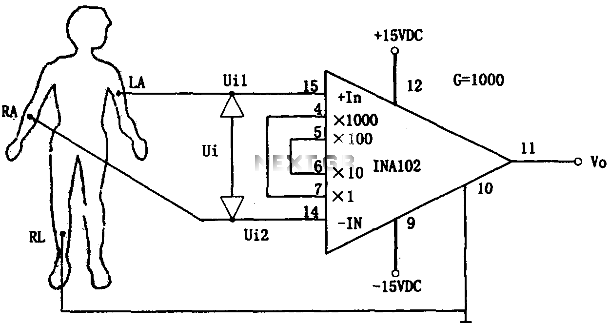
This document outlines a preamplifier circuit designed for measuring human biological signals, such as ECG and EEG. These biological signals are typically weak and require high amplification circuits. The circuit utilizes a low-power integrated operational amplifier, INA102. The INA102...
The objective is to enhance information transmission through the distribution of articles. For any issues related to article content, copyright, or other concerns, please contact us via email at [email protected] within 15 days. Prompt action will be taken to...
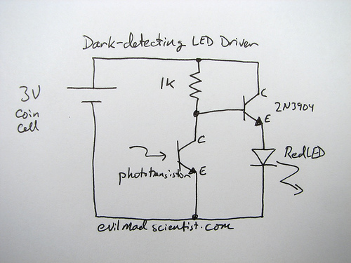
The following circuit illustrates a simple and inexpensive dark-detecting LED circuit. Features include the use of photoresistors, specifically a photocell or LDR, and an LED. This circuit utilizes a light-dependent resistor (LDR) as the primary sensing element. The LDR exhibits...
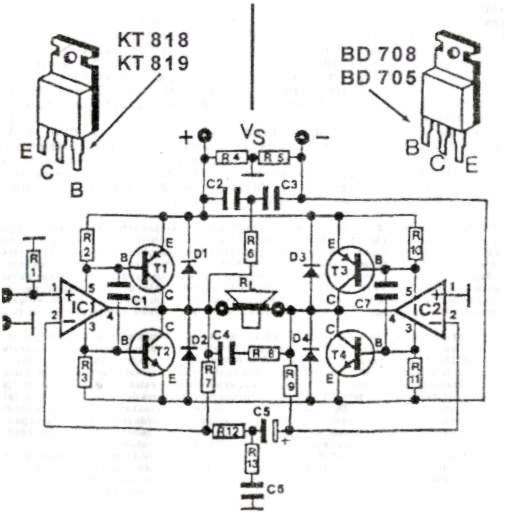
This audio amplifier circuit provides up to 200 W of high-quality output for loudspeakers with impedances ranging from 4 to 16 ohms. The operating voltage is between 24 and 36 V, with a maximum current of 5 A. The audio...
The amplifier circuit utilizing the STK4050 integrated circuit (IC) is known for its robustness and high quality. This article presents a 200-watt power amplifier circuit based on the STK4050. The circuit features an advanced auto wiring diagram with color-coded...