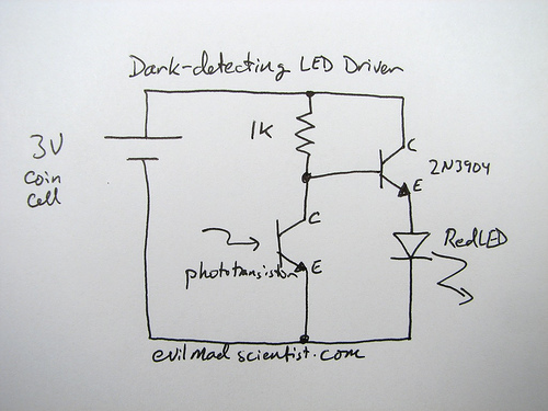
Simple Dark-Detecting LED Circuit With 2N3904 Transistor

The following circuit illustrates a simple and inexpensive dark-detecting LED circuit. Features include the use of photoresistors, specifically a photocell or LDR, and an LED.
This circuit utilizes a light-dependent resistor (LDR) as the primary sensing element. The LDR exhibits a high resistance in low-light conditions and a low resistance in bright light, making it an ideal component for detecting ambient light levels. When the light intensity falls below a certain threshold, the resistance of the LDR increases, which triggers the circuit to turn on the LED.
The circuit typically consists of a power source, an LDR, a resistor, and an LED. The LDR is connected in a voltage divider configuration with a fixed resistor. This configuration allows the voltage across the LDR to vary with light intensity. When the light level decreases, the voltage drop across the LDR increases, which can be used to activate a transistor or a relay that powers the LED.
The LED is connected in such a way that it lights up when the transistor is turned on, indicating that the ambient light level has dropped below the predefined threshold. This circuit can be used in various applications, such as automatic night lights, garden lights, or security systems, where it is essential to detect darkness and activate a light source accordingly.
The simplicity and low cost of this dark-detecting LED circuit make it an excellent choice for both amateur and professional electronics projects. Proper selection of the LDR and resistor values is crucial for achieving the desired sensitivity and response time of the circuit.The following circuit shows about A Simple and Cheap Dark-Detecting LED Circuit. Features: Photoresistors are reliable, photocell or LDR, LED .. 🔗 External reference


