
central locking interface

To implement the described functionality, a relay interface circuit can be designed to interface between the car alarm and the central locking system. The circuit will require two relays rated for the appropriate voltage and current to handle the solenoid activation of the central locking mechanism.
The first step involves identifying the alarm signal output, which is typically a wire leading from the alarm control unit. This signal should be monitored to determine its state (high or low). A microcontroller or a simple transistor circuit can be employed to detect the state of the alarm signal. When the alarm is activated (high state), the microcontroller or transistor will trigger the relay circuit.
The relay circuit consists of two relays, each capable of handling the current required by the central locking system. The relays should be connected in parallel, ensuring redundancy and reliability. The contacts of these relays will be wired to the master solenoid of the central locking system.
To convert the toggle of the alarm signal into a brief pulse, a monostable multivibrator (such as a 555 timer configured in monostable mode) can be used. This component will generate a short pulse each time the alarm signal toggles, ensuring that the relays are activated momentarily to engage the locking mechanism without causing continuous activation.
Additional components such as diodes should be included in the circuit to protect against back EMF generated by the relays when they are deactivated. Proper power supply decoupling and filtering should also be implemented to ensure stable operation of the microcontroller or transistor circuit.
The overall design will ensure that the car alarm can effectively control the central locking system, providing enhanced security and convenience for the vehicle owner.Some cheap car alarms do not have a connection for the central locking system. However, in most it should be possible to find a point in the alarm circuit which is high when the alarm is activated and low when it is off. This signal can then be used to drive this relay circuit to operate the central locking system. The interface circuit converts e ach toggle of the alarm signal to a brief pulse to operate the two relays which then are then connected in parallel with appropriate contacts on the master solenoid in the central locking system. 🔗 External reference
Related Circuits
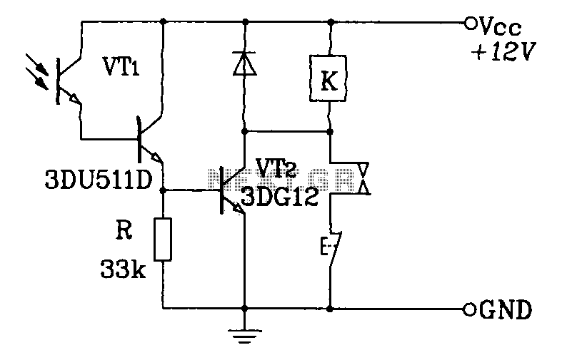
A Darlington phototransistor serves as the primary component for the photoelectric function within a self-locking control relay circuit. The circuit utilizes a Darlington phototransistor, which is known for its high current gain and sensitivity to light. This device is configured...
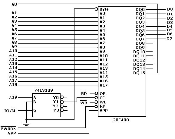
Flash memory, also known as flash RAM, is a type of non-volatile semiconductor memory device that retains stored data even when not powered. It is an enhanced version of electrically erasable programmable read-only memory (EEPROM). The primary distinction between...
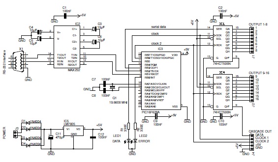
This basic PIC-based RS-232 serial interface can control up to 120 digital TTL outputs. The described circuit utilizes a PIC microcontroller to facilitate communication via the RS-232 protocol, which is a standard for serial communication. The interface primarily serves to...
U7 is a 6510 microprocessor. One of the features of the 6510 is a built-in parallel I/O port (P0-P5). Pins P3 to P5 control most of the cassette interface circuitry. The P3 pin of U7 outputs the write data...
The 5 V from USB appears to be powering the LED on the laptop power brick. Therefore, even when the power brick is turned off at the wall outlet, the LED remains illuminated. When the USB is unplugged, the...
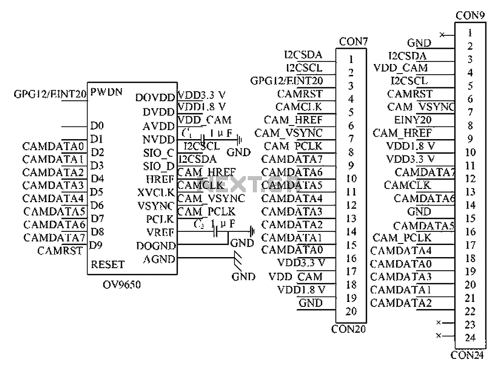
The circuit principle involves the OV9650 processor, which interfaces through three components: the SCCB interface, the data output interface, and the control interface. The SCCB interface is responsible for transferring initialization parameters from the processor's internal registers. It utilizes...