
computer Interface Circuit

The described circuit utilizes a PIC microcontroller to facilitate communication via the RS-232 protocol, which is a standard for serial communication. The interface primarily serves to control a maximum of 120 digital TTL (Transistor-Transistor Logic) outputs, enabling the microcontroller to manage multiple devices or components simultaneously.
In this configuration, the PIC microcontroller is programmed to interpret incoming serial data and convert it into corresponding TTL-level signals. The RS-232 standard operates at voltage levels that are not directly compatible with TTL logic, thus a level-shifting circuit may be integrated to ensure proper signal translation between the RS-232 interface and the TTL outputs.
The circuit typically includes a MAX232 or similar level-shifting IC, which converts the RS-232 voltage levels to TTL levels suitable for the PIC microcontroller. The output from the microcontroller can be connected to a series of transistors or relay drivers that control the desired digital outputs. Each output can be independently activated or deactivated based on the commands received via the RS-232 interface.
Additionally, the design may incorporate various protection mechanisms, such as diodes for back EMF protection when driving inductive loads, and resistors to limit current to the outputs. Proper decoupling capacitors should also be used to stabilize the power supply and reduce noise.
Overall, this PIC-based RS-232 serial interface can serve a wide range of applications, from simple control systems to more complex automation tasks, providing a reliable means of communication and control for digital devices.This basic PIC-based RS-232 serial interface can control up to 120 digital TTL outputs.. 🔗 External reference
Related Circuits
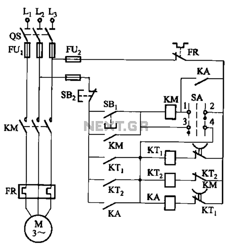
The circuit illustrated in Figure 3-78 utilizes two relays for automatic control, featuring a more complex line structure. This configuration allows for intermittent motor operation. Additionally, it can operate continuously when switch SA is positioned to the right. The circuit...

All the capacitors are present to block DC signals; however, the values of capacitance are crucial, and it is necessary to determine the value of Co. Rin denotes the source resistance, which is not an integral part of the...

This circuit for an intercom is a stand-alone electronic communications system designed for limited or private dialogue. The schematic illustrates the application circuit of the LM390 in the intercom configuration. Gain control can be achieved by capacitively coupling a...
A pH meter is a precise voltmeter that measures the generated voltage of pH electrodes. The demand for such a meter is significant. A pH meter operates by utilizing a combination of a glass electrode and a reference electrode. The...
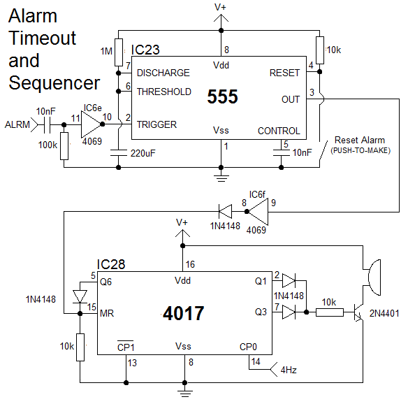
The clock is constructed using 25 CD4000 integrated circuits (ICs), three 555/556 ICs, and several discrete components. It features an alarm and a method for setting the time that is typically only seen in microcontroller designs. The complexity of...
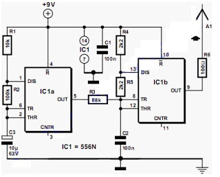
The output frequency alternates between approximately 2100 Hz and 2200 Hz. This unique test signal is easily distinguishable from other potential signals. Resistor R6 is connected to a wire, approximately ten centimeters long, which serves as the antenna. The...