
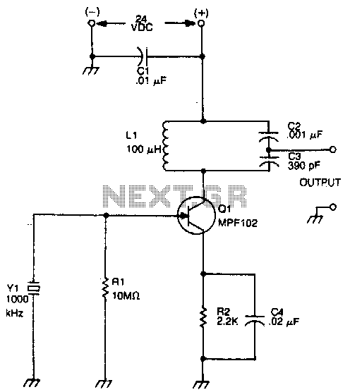
Ceramic resonator oscillator

The main purpose of having a ceramic filter is to serve as a bandpass filter with sharp filter characteristics. The filter is designed to allow signals within a specific frequency range to pass while attenuating signals outside of this range. A test rig for a 455kHz ceramic filter typically includes a signal generator sweeping frequencies from 400kHz to 500kHz, with resistors used for impedance matching.
The attenuation characteristics of ceramic filters are critical in determining their performance. For instance, at the center frequency of 455kHz, the attenuation is ideally 0dB, indicating no loss of signal amplitude. However, as the frequency deviates from this center point, the attenuation increases. For example, at 440kHz and 470kHz, a blue ceramic filter may show an attenuation of 10dB, meaning the output signal is reduced to approximately 31.6% of the input signal. In contrast, a red ceramic filter exhibits a sharper response, achieving 40dB attenuation at the same frequencies, resulting in the output being only 1% of the input. This characteristic makes the red ceramic filter more effective for applications requiring precise frequency selection and minimal signal loss at the desired frequency.
In summary, the MC3371 receiver circuit effectively utilizes a ceramic filter to isolate the desired 455kHz signal from the mixed RF input, with the ceramic resonator providing a cost-effective alternative to crystal oscillators in various electronic applications. The design emphasizes the importance of filter characteristics in ensuring signal integrity and performance in communication systems.This receiver is MC3371. Pin 16 is the RF input to the mixer and pin1 and pin2 is the local oscillator. The product comes out at pin 3. Imagin you want to receive at 100MHz. The local oscillator is set to 100.455kHz and when the mixer mix the RF (100MHz) with the osc (100.455MHz) the product will be 455kHz and lots of other frequency products. What we want is only the 455kHz signal. And it is here the ceramic filter comes handy. It filter away almost everything except 455kHz +/- 10kHz. The signal goes to pin 5 and limits and amplifyes. A FM-demodulator brings out the sound from the 455kHz signal with the help of a quad coil. The audio signal amplifyes and comes out at pin 9. The ceramic resonator is mostly used as oscillator in different application. The ceramic resonator is often used instead of crystal because of it's lower price. The frequency accuracy is not as good as a crystal but in many application the accuracy is not critical. The ceramic resonator use the mechanical resonance of piezoelectric ceramics.(Generally lead zirconium titanate: PZT.) The figure at right shows the symbol for a ceramic resonator.
The impedance and phase characteristics measured between the terminals are shown in figure below. The ceramic componets are made of high stability piezoelectric ceramics that functions as a mechanicalresonator. The frequency is primary adjusted by the size and thikness of the ceramic element. Typical application includes TVs, VCRs, telphones, remote controls and radios. What is the main purpose to have a ceramic filter? The filter is actually a bandpass filter with sharp filter characteristic. Figure at right shows a test rig for a 455kHz ceramic filter. At the input you have a signal generator and at the output you have RF voltmeter. The signal generator will sweep the frequency from 400kHz to 500kHz. There is some resistor to impedance match the filter. Look now at the figure below wich shows the attenuation of the filter. dB conversion?? Attenuation in dB = 20*log (attenuation in times) Example: 100 time attenuation give 40dB attenuation because 40dB = 20 * log (100) This diagram show attenuation versus the frequency for 3 different type of ceramic filters.
If we start to look at 455kHz, we can see that the attenuation is 0dB (no attenuation). Every signal wich is 455kHz will pass through the filter witout any attenuation. If the frequency is more or less than the 455kHz the attenuation increase. Look at the blue line. At 440kHz and 470kHz the attenuation has reached 10dB (equal to 3.16 times). The output signal (RF V.M) is only 31.6% of the input signal (S.S.G). The red line is dropping faster and at 440kHz and 470kHz the attenuation has reached 40dB (equal to 100 times). The output signal is only 1/100 of the input signal. The red ceramic filter is much sharper than the blue one. 🔗 External reference
Related Circuits
The drain of the JFET Miller oscillator is tuned to the resonant frequency of the crystal by an LC tank circuit. The JFET (Junction Field-Effect Transistor) Miller oscillator is a type of oscillator circuit that utilizes the properties of a...
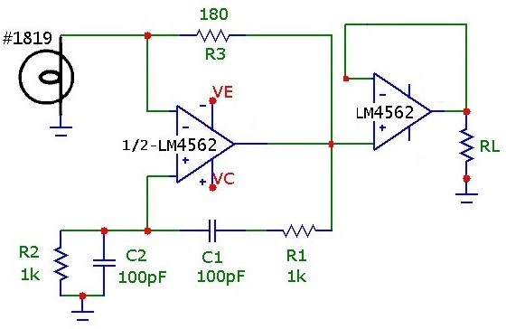
The classic Wien-Bridge oscillator, with incandescent lamp nonlinear stabilization, provides a low distortion sine wave source. A thorough and clear discussion of the Wien-Bridge oscillator is provided in Malvino's Electronic Principles. Using an inexpensive op-amp with sufficient bandwidth and...
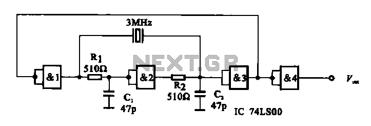
A crystal oscillator circuit is composed of several gates. Figure (A) illustrates a crystal oscillator circuit operating at 1 MHz, while Figure (B) depicts a 20 MHz crystal oscillator circuit. Figure (C) represents a variable crystal oscillator circuit with...
Op-amps have been widely used in low-frequency oscillators. Op-amps, or operational amplifiers, are versatile components frequently utilized in the design of low-frequency oscillators. These devices are capable of generating periodic waveforms, such as sine, square, or triangular waves, which are...
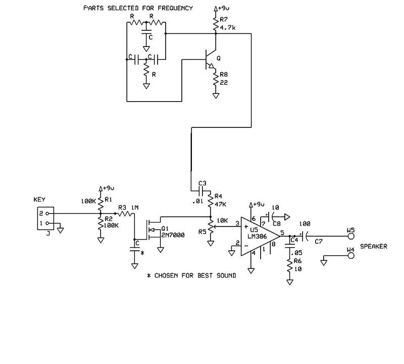
A schematic for a code practice oscillator is needed, which can be connected to a keyer. The desired setup involves using a Picokeyer, allowing the oscillator to be plugged into the key jack of the Picokeyer. The output should...
One of the simplest methods of metal detection is through a beat frequency oscillator. The circuit consists of two balanced oscillators: one provides a reference signal, while the other acts as the detector element. The frequency of the reference...