
Miller oscillator

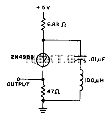
The JFET (Junction Field-Effect Transistor) Miller oscillator is a type of oscillator circuit that utilizes the properties of a JFET to generate oscillations. In this configuration, the drain terminal of the JFET is connected to an LC tank circuit, which consists of an inductor (L) and a capacitor (C). This tank circuit is crucial for determining the oscillation frequency.
The resonant frequency of the LC tank circuit is given by the formula:
\[ f_0 = \frac{1}{2\pi\sqrt{LC}} \]
where \( f_0 \) is the resonant frequency, \( L \) is the inductance, and \( C \) is the capacitance. The design of the tank circuit allows it to resonate at the same frequency as the crystal, ensuring that the oscillator operates efficiently.
The JFET in the Miller oscillator configuration also provides gain and feedback. The feedback loop is formed by connecting a portion of the output signal from the drain back to the gate of the JFET. This feedback is essential for sustaining oscillations. The gain provided by the JFET must be sufficient to overcome losses in the circuit to maintain continuous oscillation.
In summary, the JFET Miller oscillator's design, which incorporates an LC tank circuit tuned to the resonant frequency of a crystal, enables the generation of stable oscillations. This configuration is widely used in applications requiring precise frequency generation, such as in radio frequency (RF) circuits and signal processing systems. Proper selection of the inductor and capacitor values is essential to achieve the desired frequency characteristics while ensuring stability and reliability in the oscillator's performance.The drain of the JFET Miller oscillator is tuned to the resonant frequency of the crystal by an LC tank circuit.
Related Circuits
This is a basic 555 squarewave oscillator used to produce a 1 kHz tone from an 8-ohm speaker. In the circuit on the left, the speaker is isolated from the oscillator by the NPN medium power transistor, which also...
The schematic diagram depicted in Figure 1 is designed to synthesize a sinusoidal waveform with a frequency range of 0.01 Hz to 1 MHz. A clock signal is supplied to the input of the binary counter IC1, with a...

A circuit is needed to drive three or more LEDs at a current of 200-350mA each, with the capability to randomly flash or strobe them at a frequency of 5-20Hz. The input power should be low-voltage DC, with a...
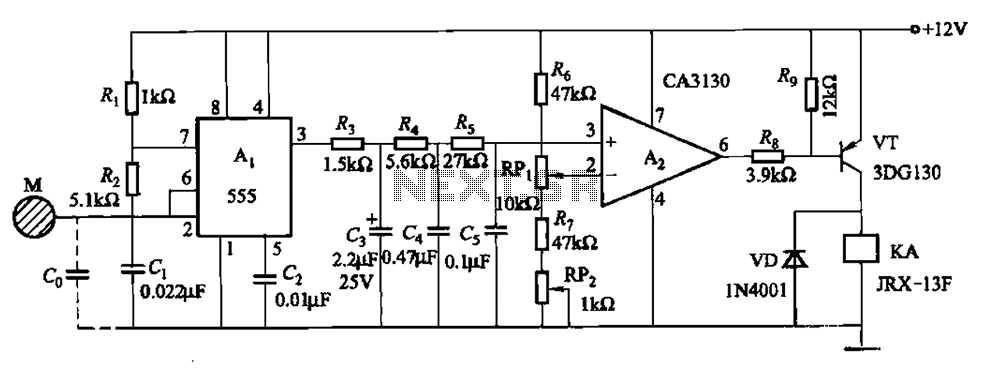
The circuit utilizes a 555 IC in conjunction with capacitors C1, C2, and a metal plate (tablet) M to create a distributed capacitance Co and resistor R1 connected to ground. Resistor R2 forms a self-excited multivibrator, while resistors R3...
Crystal oscillators are devices where a specially cut crystal regulates the frequency. Crystal-controlled oscillators are the standard method for maintaining the frequency of radio transmitting stations within their designated limits. These oscillators typically produce an output that is highly...
The capacitor charges until the switching voltage is reached. When the switch (SUS) is activated, the inductor causes the current to oscillate. When the current through the switch drops below the holding current, the device turns off, and the...