
Charge amplifier circuit diagram OPA128

A charge amplifier serves a critical role in signal processing, particularly when dealing with piezoelectric sensors that generate minimal charge output. The fundamental operation of a charge amplifier relies on its ability to convert the charge signal into a voltage signal while maintaining high fidelity. The high input impedance of the charge amplifier ensures that the sensor's output is not loaded, preserving the integrity of the signal.
The OPA128 operational amplifier is specifically chosen for its characteristics that align well with the requirements of charge amplification. With a low input bias current and high input resistance, the OPA128 minimizes any additional noise or distortion that could arise from the amplifier itself. This is crucial in applications where the signal levels are very low, as even minor perturbations can lead to significant inaccuracies in the output.
In the schematic, the charge amplifier configuration typically includes the OPA128 connected in a feedback loop that allows for the transformation of the input charge signal into a proportional output voltage. The feedback capacitor is a key component, as it determines the gain of the amplifier based on the charge it receives. The design must ensure that the selected feedback components are optimized to match the characteristics of the piezoelectric sensor being used.
Overall, the design of a charge amplifier circuit utilizing the OPA128 is essential for applications requiring precise measurement and amplification of low-level signals from piezoelectric devices. This configuration provides a reliable solution for accurately capturing and processing these signals in various electronic systems.The so-called charge amplifier means for amplifying the signal charge from the piezoelectric device amplifying circuit . Such high internal impedance of the amplifier signal source, while its charge very weak signal, the current source is formed only pA level, which requires a charge amplifier with a high input resistance and low bias current, otherwise when the amplifier bias current and signal current is similar to the bias current signal may be overwhelmed, and can not achieve normal zoom. Further, high-impedance (1012 ) in the usual sense amplifier circuit can not be used. Often used for this type of electrostatic integrated operational amplifier OPA128 amplifier circuit composed.
As shown for the charge amplifier OPA128 constituted.
Related Circuits
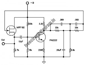
The following circuit illustrates a stable 60 Hz frequency signal generator circuit diagram. Features include a 0.068 µF capacitor incorporated within a feedback loop, allowing for DC-to-AC conversion. This circuit is designed to generate a stable 60 Hz sine wave...
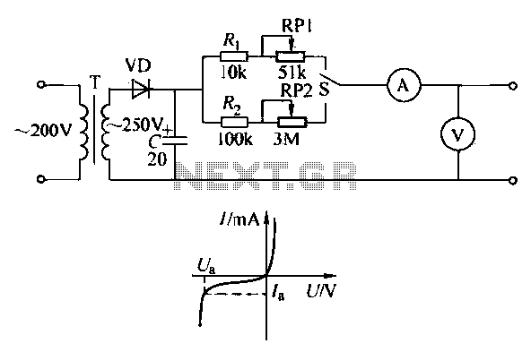
To ensure proper operation of the transistor in a circuit, it is essential to measure the reverse breakdown voltage of the transistor. This is particularly important for tubes with high reverse breakdown voltage requirements, such as those used in...
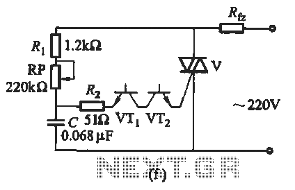
The introduction for a unidirectional thyristor trigger circuit is also applicable to the TRIAC. Various configurations are presented in Figure 16-28. Figures 16-28 (a) and (b) illustrate a direct trigger circuit; Figure 16-28 (c) depicts a dual diode trigger...
This is a compact LED flasher circuit designed using the 555 timer integrated circuit (IC), powered by two 1.5V batteries. The circuit can function as a flashing metronome, dark room timer, reminder, or for other similar applications. In the...
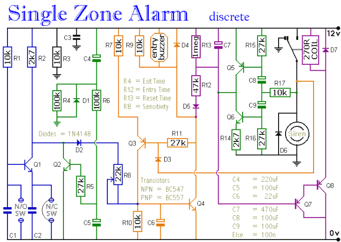
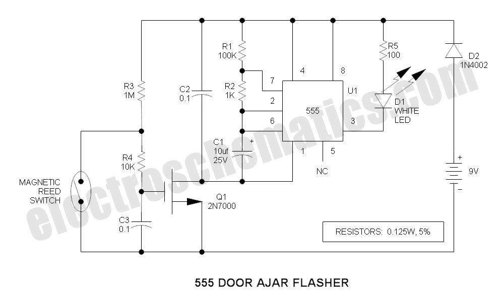
The circuit includes automatic entry and exit delays, a timed bell cut-off, and a system reset feature. It accommodates both normally open and normally closed switches, making it compatible with common input devices such as pressure mats, magnetic reed...
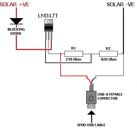
A solar charger for an iPod is no more difficult than creating a solar battery charger. Built-in iPod batteries operate at 3.7 Volts, with capacity (measured in mAh) varying by iPod model—e.g., 1,200mAh for a 2nd Gen, 850mAh for...