
Single Zone AlarmCircuit - Project

The described circuit operates as a security system, integrating various functionalities for enhanced user experience and safety. The automatic entry and exit delays serve to provide users with ample time to enter or exit the premises without triggering the alarm unintentionally. The timed bell cut-off feature is particularly useful for minimizing disturbances while still ensuring security.
The system's compatibility with different types of switches and sensors allows for versatile applications in various environments. The inclusion of pressure mats and PIRs enhances the system's ability to detect movement, while magnetic reed contacts and foil tape provide additional security options for door and window monitoring.
The fault detection mechanism, indicated by the sounding buzzer, is a critical safety feature, alerting users to potential vulnerabilities in the system. This proactive approach helps to maintain the integrity of the security setup.
Adjustable parameters for exit delay, entry delay, and bell cut-off times allow customization based on user preferences or specific situational requirements. This flexibility is essential in environments where different security protocols may be needed.
The design considerations regarding the timing components, such as capacitors and resistors, emphasize the importance of precision in timing applications. The option to simplify the circuit by omitting certain components allows for a balance between functionality and ease of use, catering to various user needs.
Inertia sensor sensitivity adjustments provide an additional layer of customization, accommodating different levels of activity in the monitored area. The ability to replace components based on the specific sensors in use ensures that the system remains adaptable and efficient.
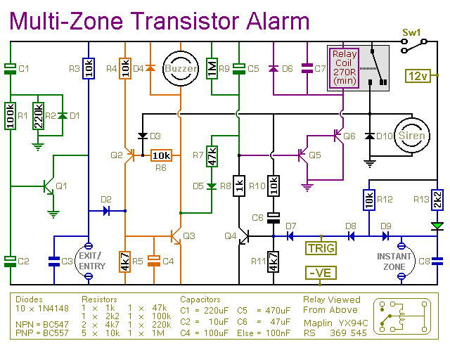
Overall, this circuit exemplifies a well-thought-out security solution, combining practical features with flexibility to meet diverse user requirements.The circuit features automatic exit and entry delays, timed bell cut-off and system reset. It has provision for normally open and normally closed switches and will suit the usual input devices (Pressure Mats, Magnetic Reed contacts, Foil Tape, PIRs and Inertia Sensors). When the power is applied, if there`s a fault the buzzer will sound and you sh ould switch off again and check for open doors, windows, etc. If everything is in order the buzzer will NOT sound and the exit delay will begin. You have about 30 seconds to leave the building. When you return the buzzer will sound. You then have about 30 seconds to switch off; otherwise the siren will sound. It will go on sounding indefinitely. However, if the building is re-secured the siren will switch off after about 10 minutes and the alarm will reset. The Exit delay, Entry delay and Bell Cut-off times can be changed by altering the values of R4, R12 & R13 respectively.
Q5 and Q6 ensure that the Entry delay and Bell cut-off timers always start with C7 either fully charged or fully discharged as required. If you can live with slightly less precise time intervals then leave out Q5, Q6, R14, R15, R16, R17, C8 & C9.
If you don`t want a Bell Cut-off at all then leave out D3 as well. The sensitivity of the Inertia Sensors is adjusted by R8. Set to minimum value, a light tap will activate the alarm. Set to maximum value, a heavy blow is required. If you are not using Inertia Sensors then replace R8 with a 27k fixed resistor. If you are not using normally open switches then leave out R1, C1 & Q1 and fit a link between R2 and C2. 🔗 External reference
Related Circuits
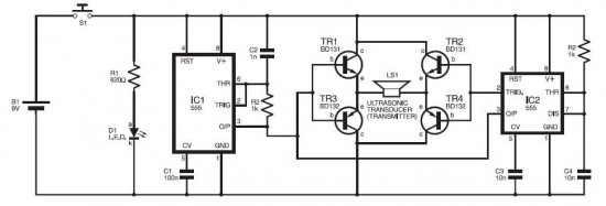
The electronic dog repellent circuit diagram below features a high-output ultrasonic transmitter designed primarily to function as a repeller for dogs and cats. The electronic dog repellent circuit utilizes an ultrasonic transmitter to emit sound waves at frequencies above the...
This is a simple transistor-based burglar alarm circuit. Its features include automatic exit and entry delays, along with a timed bell cut-off and reset. It is designed to be used with standard types of normally-closed input devices such as...
A digital micro-ohm meter is essential for assessing the condition of shunts used in the Electrochemical Analysis & Diagnostics Laboratory (EADL) at Argonne National Laboratories. A shunt is essentially a small resistor utilized for current measurement. The micro-ohmmeter will...
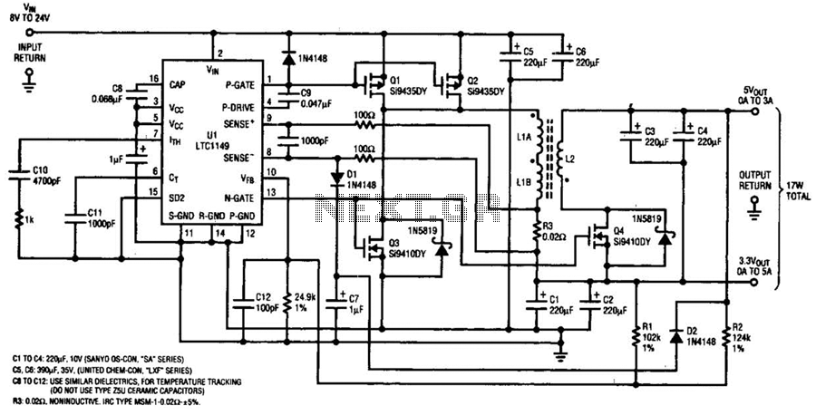
One LTC 1149 synchronous switching regulator can deliver both 3.3 and 5 V outputs. The design's simplicity, low cost, and high efficiency make it a strong contender for portable, battery-powered applications. The circuit described accepts input voltages from 8...
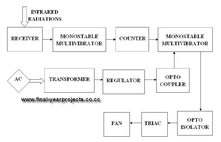
This report presents a comprehensive overview of a mini project titled "Remote Controlled Fan Regulator," developed in accordance with the curriculum requirements for the sixth semester of the Bachelor of Technology degree in Electrical and Electronics Engineering. The report...
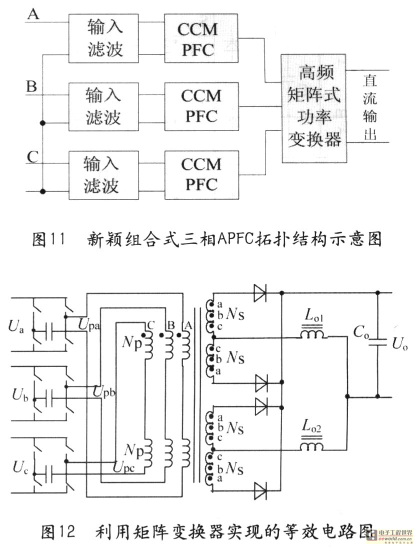
Tape isolate single-phase power factor correction (PFC) that utilizes DC/DC converters, consisting of two cables. The three-phase PFC is formed by connecting three single-phase PFCs in parallel at the output. This configuration is based on a matrix-type DC/DC converter...