
charge monitor for 12V car battery circuit diagram

The described circuit for monitoring lead-acid battery charge levels employs a systematic approach to ensure optimal battery health. The use of the LM3914 IC allows for a precise visual representation of the battery's voltage range, which is critical for maintaining the battery's operational limits. The integration of the 74LS147 encoder and 74LS04 inverter facilitates a seamless transition from analog voltage levels to a digital format, which is then interpreted by the 74LS247 decoder/driver to present a clear numerical output on the LTS-542 display.
The design incorporates protective features through the buzzer system, which acts as an alert mechanism for users, thereby preventing potential damage to the battery from overcharging or deep discharging. This proactive measure not only extends the life of the battery but also enhances the reliability of the entire system it supports. Calibration procedures outlined in the design ensure that the monitoring system operates accurately, providing users with confidence in the displayed readings. Overall, this circuit represents an effective solution for continuous battery monitoring, combining ease of use with essential protective features.A battery is a vital element of any battery-backed system. In many cases the battery is more expensive than the system it is backing up. Hence we need to adopt all practical measures to conserve battery life. As per manufacturer`s data sheets, a 12V rechargeable lead-acid battery should be operated within 10. IV and 13. 8V. When the battery charges higher than 13. 8V it is said to be overcharged, and when it discharges below 10. IV it can be deeply discharged. A single event of overcharge or deep discharge can bring down the charge-holding capacity of a battery by 15 to 20 per cent. It is therefore necessary for all concerned to monitor the charge level of their batteries continuously.
But, in practice, many of the battery users are unable to do so because of non-avail ability of reasonably-priced monitoring equipment. The circuit idea presented here will fill this void by providing a circuit for monitoring the charge level of lead-acid batteries continuously.
The circuit possesses two vital features: Input from the battery under test is applied to LM3914 1C. This applied voltage is ranked anywhere between 0 and 10, depending upon its magnitude. The lower reference voltage of 10. IV is ranked `0` and the upper voltage of 13. 8V is ranked as `10. ` (Outputs 9 and 10 are logically ORed in this circuit. ) This calibration of reference voltages is explained later. 1C 74LS147 is a decimal-to-BCD priority encoder which converts the output of LM3914 into its BCD complement. The true BCD is obtained by using the hex inverter 74LS04. This BCD output is displayed as a decimal digit after con version using IC5 (74LS247), which is a BCD-to-seven-segment decoder/driver.
The seven-segment LED display (LTS-542) is used because it is easy to read compared to a bar graph or, for that matter, an analogue meter. The charge status of the battery can be quickly calculated from the display. For instance, if the display shows 4, it means that the battery is charged to 40 per cent of its maximum value of 13.
8V. The use of digital principles enables us to employ a buzzer that sounds whenever there is an overcharge or deep discharge, or there is a need to conserve battery charge. A buzzer is wired in the circuit such that it sounds whenever battery-charge falls to ten per cent. At this point it is recommended that unnecessary load be switched off and the remaining charge be conserved for more important purposes.
Another simple combinational logic circuit can also be designed that will sound the buzzer when the display shows 9. Further charging should be stopped at this point in order to pre vent overcharge. For calibrating the upper and lower reference levels, a digital multimeter and a variable regulated power supply source are required.
For calibrating the lower reference voltage, follow the steps given below: The higher reference voltage is calibrated similarly by setting the power supply to 13. 8V and varying preset VR1 until reading on the display just changes from 8 to 9. Disclaimer: All the information present on this site are for personal use only. No commercial use is permitted without the prior permission from authors of this website. All content on this site is provided as is and without any guarantee on any kind, implied or otherwise.
We cannot be held responsible for any errors, omissions, or damages arising out of use of information available on this web site. The content in this site may contain COPYRIGHTED information and should not be reproduced in any way without prior permission from the authors.
🔗 External reference
Related Circuits
The design objective was to produce an hFE tester with switched collector currents for the DUT (Device Under Test) covering a range suitable for the selection and matching of output transistors for amplifiers such as the JLH Class-A, ESP...
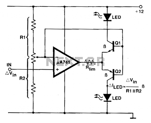
An operational amplifier (op amp) is utilized as a comparator and as a current sink for an LED. The output voltage of the amplifier varies by approximately 1.4 V based on the direction of the current. At any given...
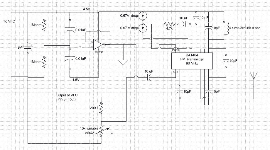
V_logic is connected to the power supply Vs and all ground are connected to the negative terminal of the battery. Fout is a square wave of varying frequency with a maximum amplitude of Vs. A voltage divider is needed...
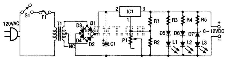
This 0- to 12-Vdc variable power supply utilizes an integrated circuit (IC) voltage regulator along with a robust transformer to deliver a dependable DC power output. The schematic illustrates that transformer T1 has a primary voltage of 120 V...
The circuit is straightforward yet capable of outstanding performance. It has been specifically designed as an amplifier for the digital sound card in a computer. Audio input can be sourced from any two-channel line-level device such as a television,...
This circuit is utilized in RS-232 serial interface and current loop circuit applications. It converts voltage signals into a 20mA current signal, with a maximum transmission rate of 1200 bits per second. The CCD IC1 and transistor T1 form...