
Computer RS-23Z serial interface current loop circuit

The circuit serves a crucial role in enabling communication between devices using the RS-232 standard, which is widely employed in serial communication. The conversion of voltage signals to a 20mA current signal is essential for maintaining signal integrity over longer distances, as current loops are less susceptible to noise compared to voltage signals.
The receiver interface circuit, comprising CCD IC1 and T1, is responsible for interpreting incoming voltage signals. The CCD IC1 is designed to handle the specific characteristics of the RS-232 signals, converting them into a format suitable for processing. The transistor T1 acts as a switch, allowing the received signals to be passed to the next stage of the circuit.
On the transmitter side, the configuration of transistors T2 and T3 is critical for the proper functioning of the circuit. When a +12V supply is applied, both T2 and T3 enter a conductive state, enabling the flow of current. This current is then used to represent the transmitted data. The design ensures that the circuit can transmit data at a rate of up to 1200 bits per second, which is sufficient for many applications that utilize RS-232 communication.
In summary, this circuit effectively bridges the gap between voltage-based and current-based communication systems, enhancing reliability and performance in serial data transmission. Its design, featuring both receiver and transmitter components, allows for seamless integration into existing systems, making it a valuable component in electronic communication applications.This circuit is used in computer RS-232 serial interface and current loop circuit interface, it can transform voltage singal into 20mA current singal, the maximum transmission rate is 1200 bits. CCD IC1, T1 form receiver interface circuit, T2, T3 constitute transmitter interface circuit. When adds +12V, T2, T3 are conduction, the current outflows from T2.. 🔗 External reference
Related Circuits
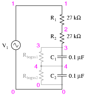
Construct the circuit and measure the voltage drops across each component using an AC voltmeter. Additionally, measure the total (supply) voltage with the same voltmeter. It will be observed that the individual voltage drops do not sum up to...
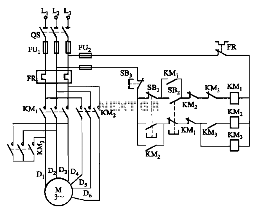
The circuit depicted in Figure 3-96 features a low-speed operation button (SBz), a high-speed operation button (SBi), and a stop button (SB3). In this configuration, a motor is connected in such a way that when the low-speed button is...
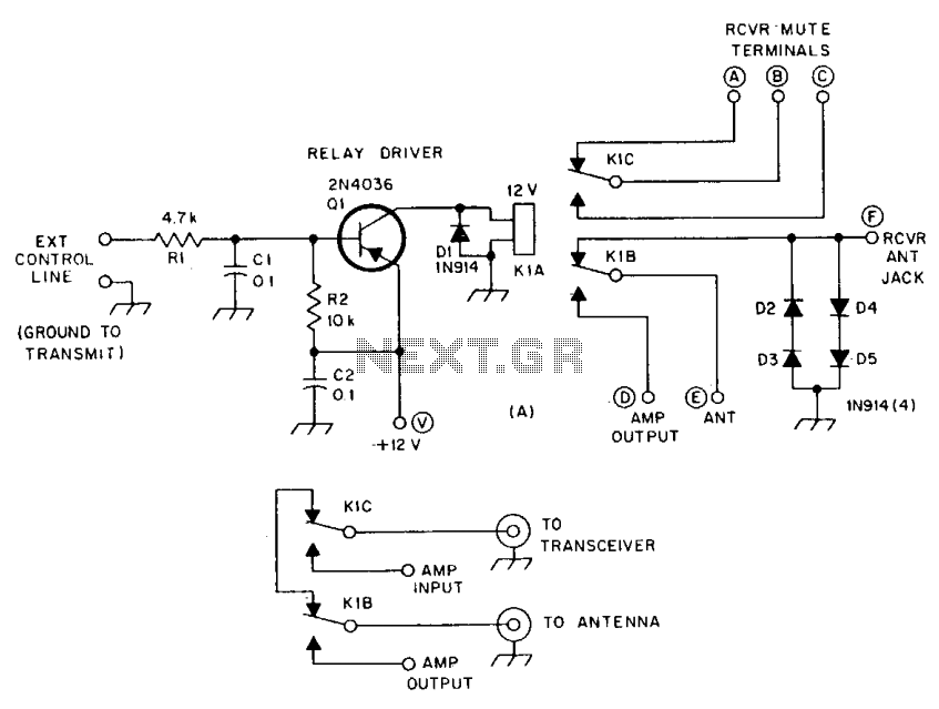
R1 and R2 are carbon composition resistors labeled as Va or Vi. K1 is a 12 V DPDT DIP relay. Illustration A demonstrates the connection of the relay contacts for use with a separate transmitter-receiver combination. The circuit is...
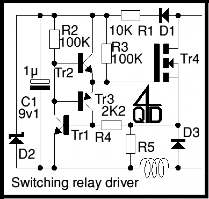
It operates by PWM (Pulse Width Modulation) - well, actually by PFM - Pulse Frequency Modulation. At power up, C1 charges up via D1 and R1. R2 will conduct, pulling the base of the emitter follower, Tr2, up and...
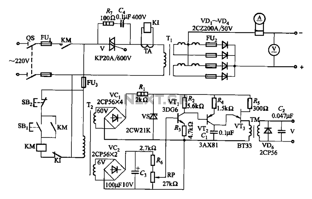
A 500A-6V single-phase power supply circuit designed for thyristor electroplating. This circuit can output a continuous DC current of 500A at 6V, which is adjustable for plating processes. It incorporates a single-junction transistor as part of the trigger circuit,...
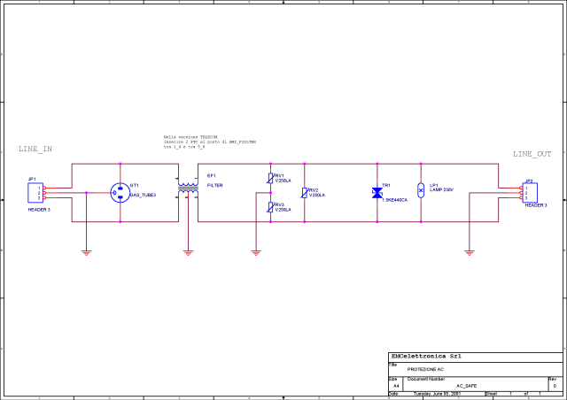
What is a circuit breaker? When is an AC power line filter or a phone line filter necessary? How can a noise filter be designed? Is it possible to create a homemade surge protector? The following circuit protection options...