
Charger circuit V

The charger circuit is designed to efficiently manage the charging process of lead-acid batteries while ensuring the safety and longevity of both the charger and the battery. The charging voltage of 14.4 V is specifically chosen to optimize the charging process for six series-connected cells, each rated at 2.4 V. By operating at a frequency of 120 Hz, the circuit effectively delivers energy in controlled pulses, which helps to minimize heat generation and prolongs the life of the battery.
The current limiting feature is a critical aspect of the design, as it prevents excessive current from flowing into the battery, which can lead to overheating and potential damage. This is particularly important for lead-acid batteries that may be in a deeply discharged state, where a high initial charging current could be detrimental. The specification of charging at one-fourth the ampere-hour rating ensures that the charging process is gentle enough to safely restore the battery's charge without causing harm.
In practical terms, for a battery with a capacity of 44 ampere-hours, the charger is configured to allow a maximum charging current of 11 A. This limit is crucial when the load impedance requires more current; the circuit's ability to enter a current limiting mode ensures that the charger can adapt to varying conditions without risking damage to its components or the battery itself. The regulation of the charging pulse amplitude to maintain an average current of 8 A further enhances the safety and efficiency of the charging process, ensuring that the battery is charged effectively while minimizing the risk of overcurrent conditions.
Overall, this charger design exemplifies a well-thought-out approach to battery management, balancing efficiency, safety, and adherence to manufacturer guidelines.The charger is based on a charging voltage of 2.4 V per cell, in accordance with most manufacturers' recommendations. The circuit pulses the battery under charge with 14.4 V (6 cells ? 2.4 V per cell) at a rate of 120 Hz. The design provides current limiting to protect the charger's internal components while limiting the charging rate to prevent damaging severely discharged lead-acid batteries.
The maximum recommended charging current is normally about one-fourth the ampere-hour rating of the battery. For example, the maximum charging current for an average 44 ampere-hour battery is 11 A. If the impedance of the load requires a charging current greater than the 11 A current limit, the circuit will go into current limiting. The amplitude of the charging pulses is controlled to maintain a maximum peak charging current of 11 A (8 A average).
Related Circuits
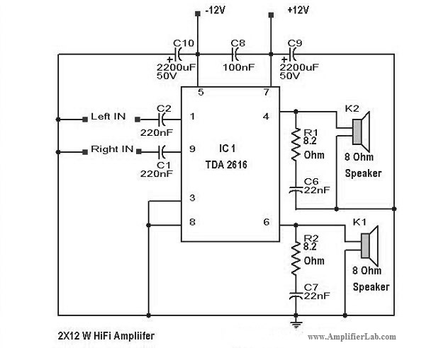
Various types of amplifiers include power amplifiers, audio amplifiers, tube amplifiers, stereo amplifiers, sensor amplifiers, RF amplifiers, sound amplifiers, and video amplifiers. Amplifiers are critical components in electronic circuits, serving to increase the amplitude of signals. Each type of amplifier...
Direct measurement circuit for soil content, assessing various parameters such as moisture, salinity, nitrogen, and pH to enhance soil quality for diverse agricultural crops. This electronic measuring circuit facilitates rapid and accurate testing of soil conditions and informs fertilization...
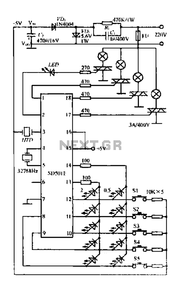
The FIG SD501E is a J tie fan integrated circuit (IC) characterized by progressive timing and three operational modes: strong, medium, and weak. It features three types of output settings and includes an electrical swing mechanism. The device is...
This example describes the use of HS101 and HS201 radio transmitter and receiver modules to control rotating color lights, functioning as a multi-channel radio remote control device suitable for small dance floors or home use. Users positioned at any...

The 555 timer integrated circuit (IC) is an exceptionally versatile component utilized in various applications, including generating clock pulses, switch debouncing, and functioning as an output transducer. The standard 555 IC is packaged in an 8-pin configuration, available in...
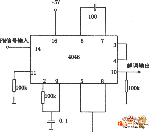
The FM demodulator circuit, as illustrated in the figure, utilizes a 4046 Phase-Locked Loop (PLL) integrated circuit to convert the intermediate frequency FM input signal into a lower frequency output. The FM demodulator circuit based on the 4046 PLL IC...