
The PLL FM demodulator (4046) circuit
")
The FM demodulator circuit based on the 4046 PLL IC operates by employing phase-locked loop techniques to achieve demodulation of frequency-modulated signals. The 4046 IC includes a voltage-controlled oscillator (VCO) and a phase comparator, which are integral to the demodulation process.
In this configuration, the FM input signal is fed into the phase comparator, which compares the phase of the incoming signal with the output of the VCO. Any phase difference detected results in an adjustment of the VCO frequency, effectively tracking the frequency variations of the FM signal. This tracking action allows the circuit to convert the frequency variations into corresponding voltage changes, which represent the original audio or data signal.
The output of the VCO is then filtered to remove high-frequency components, resulting in a low-frequency output that is a replica of the original modulating signal. Additional components such as resistors and capacitors may be included in the circuit to set the bandwidth and stability of the PLL, ensuring optimal performance for the specific FM signals being demodulated.
Overall, the 4046 PLL-based FM demodulator circuit is a robust solution for demodulating FM signals, suitable for various applications in communication systems where reliable and accurate signal processing is essential.See as the figure, the FM demodulator circuit consists of 4046 PLL particles, the intermediate FM input signal is demodulated into the low frequency by the circuit.. 🔗 External reference
Related Circuits
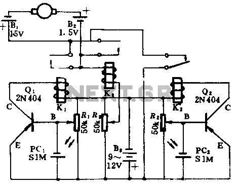
In the absence of light, photocells PC1 and PC2 exhibit high resistance, causing transistors Q1 and Q2 to remain off, which prevents the relay contacts K1 and K2 from closing. The battery B3 is connected through a potentiometer Rs,...
This amplifier circuit integrates the LT1010 with a fast discrete stage and employs an LT1008-based DC stabilization loop. It features a differential stage that operates in a single-ended configuration. The described amplifier circuit is designed to enhance signal amplification while...

Digital Command Control (DCC) provides significant advantages over traditional DC analog control systems, primarily due to its simplified wiring. DCC enables the individual control of multiple locomotives on the layout without requiring electrical isolation of track sections. The main...
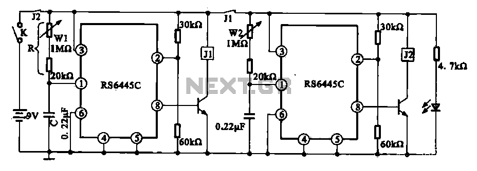
The timing integrated circuit (IC) RS6445C functions as a blocking oscillator. It features two segments, WI and W2, which are utilized to adjust the working time and the closure time. These adjustments can be continuously set within a range...
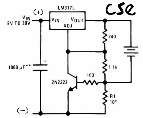
This is a straightforward charger designed for 9V to 30V batteries, primarily operated by the IC LM317L and a 2N222 transistor. It utilizes direct input DC voltage, and a recommended capacitor of 1000µF is included for filtering the output...
This precise one-pulse-per-second clock is constructed using a few common components and is driven by a 50 or 60 Hertz mains supply without any direct connection to it. A beep or a metronome-like click, along with a visible flash,...