
Charging circuit from the DC power supply switching power supply control

The charging circuit described is designed to operate with a DC power supply, utilizing a switching power supply control mechanism. This type of circuit is commonly employed in applications where efficient energy transfer and regulation are critical, such as in battery charging systems.
The circuit typically consists of several key components, including a switching regulator, input and output capacitors, diodes, and control logic. The switching regulator is responsible for converting the input DC voltage to a regulated output voltage suitable for charging a battery or powering a load. It operates by rapidly switching the input voltage on and off, which allows for efficient energy conversion and minimal heat generation.
Input capacitors are used to filter the incoming voltage, ensuring a stable supply to the switching regulator. Output capacitors are crucial for smoothing the output voltage and minimizing voltage ripple, which is essential for sensitive electronic components and batteries.
Diodes may be included in the circuit to prevent reverse current flow, protecting the power supply and connected devices from potential damage. The control logic, which may consist of operational amplifiers or microcontrollers, regulates the switching frequency and duty cycle of the regulator, adjusting the output based on the load requirements and battery state.
Overall, this charging circuit is characterized by its ability to efficiently manage power delivery from a DC source, making it suitable for a wide range of applications, including consumer electronics, electric vehicles, and renewable energy systems. Proper design and implementation of the circuit components are essential for achieving optimal performance and reliability. Charging circuit from the DC power supply switching power supply control
Related Circuits
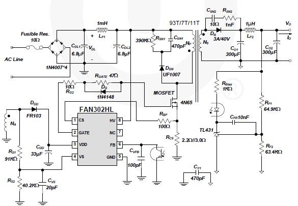
A simple 5-volt switching power supply electronic circuit project can be designed using the FAN302HL, a highly integrated PWM controller integrated circuit. This IC provides several features that enhance the performance of general flyback converters. The constant-current control of...
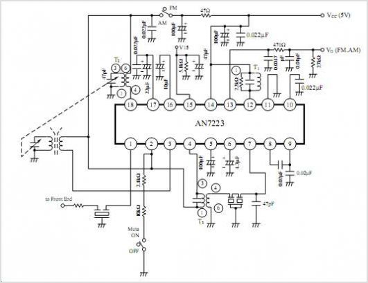
The following circuit illustrates a VHF pre-amplifier circuit diagram. This circuit utilizes the BFS17 transistor. Features: designed for VHF applications. The VHF pre-amplifier circuit is essential for enhancing weak radio frequency signals in the VHF (Very High Frequency) range, typically...
UART, GPS. This application note illustrates how to integrate a GPS module SC16C2552B into a navigation system using a Philips UART. With the rapid advancement of GPS (Global Positioning System) technologies, GPS is being increasingly utilized across various sectors....
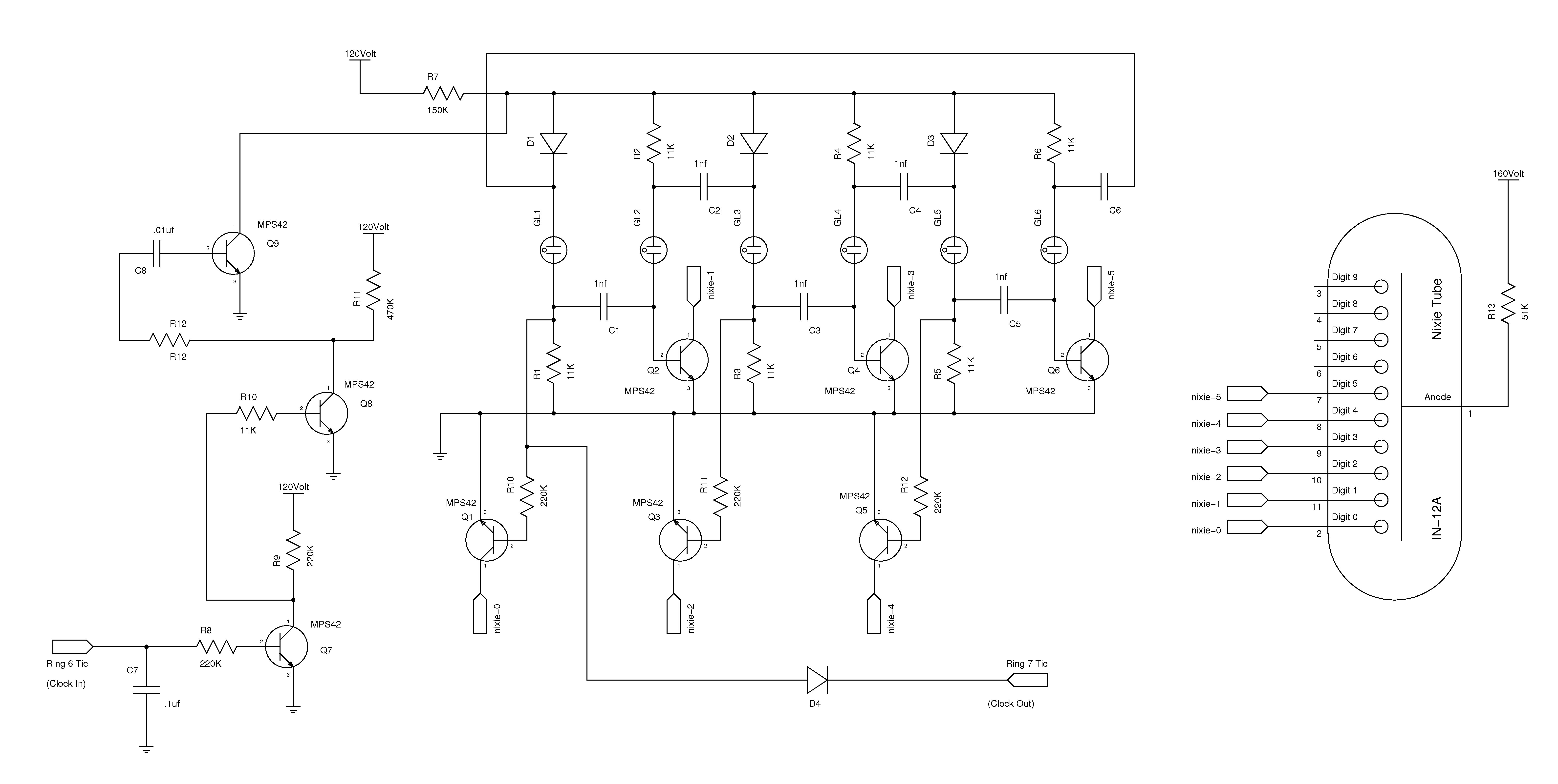
The nixie tube clock consists of a high-voltage power supply, seven ring counters, and an Atmel AVR processor. The power supply is shown in Schematic 1. It takes 12 volts AC and converts it to DC, which drives the...
It is necessary to adjust the 10K potentiometer while aiming the device at the television to obstruct the infrared rays from the remote control. This adjustment can be achieved through a process of trial and error. The circuit in question...
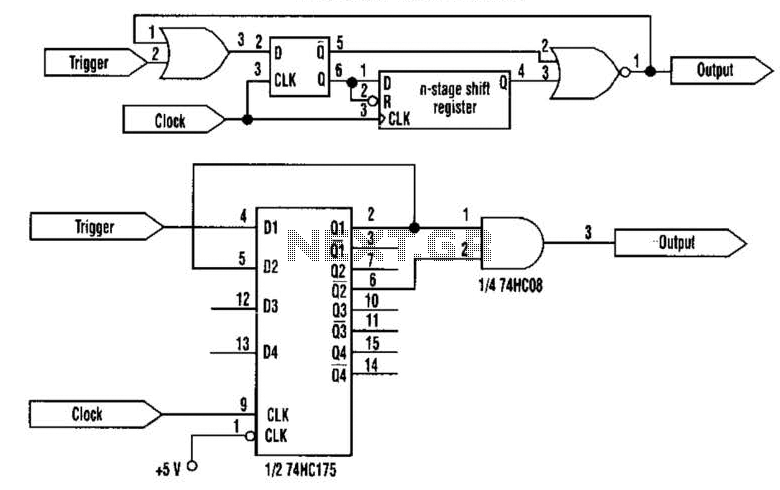
This approach utilizes a Hip-Hop, a shift register, and two gates (A). Before the one-shot pulse, the output of the NOR gate is 0. Consequently, the data input of the D-type flip-flop is equivalent to the trigger. When a...