
Christmas lights consisting of a circuit diagram of optocoupler

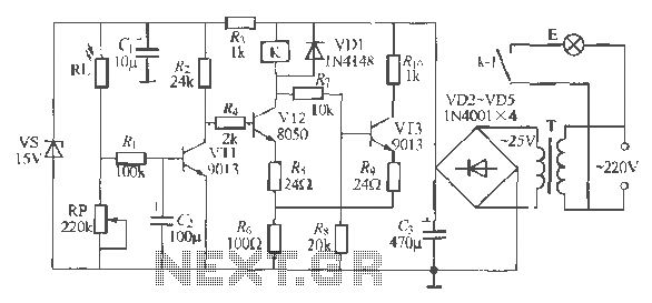
The described Christmas lights circuit utilizes an NE555 timer integrated circuit (IC1) configured in a non-stable mode to create a continuous oscillation that controls the brightness of the lights (HL). The circuit's operation begins when power is applied, allowing the timer to generate a square wave output. The frequency of this oscillation is determined by the values of resistors R1 and R2, along with capacitor C1, which set the timing intervals for the charging and discharging cycles.
As the output from pin 3 of the NE555 goes high, capacitor C3, which is connected to the circuit, begins to discharge through the optical isolator IC2 (CN25). This discharge process causes the brightness of the lights (HL) to decrease gradually. The optical isolator serves as a safety mechanism, ensuring that the high voltage present in the lighting circuit does not affect the low voltage control circuit.
Once the lights reach their minimum brightness, the NE555 timer output transitions low, allowing capacitor C3 to recharge. This recharging phase enables the lights to gradually brighten again, completing the cycle. The smooth transitions between bright and dim states create an aesthetically pleasing effect, ideal for festive decorations. The entire circuit is designed to provide a visually appealing illumination effect while ensuring reliable operation through the use of standard electronic components.
In summary, this Christmas lights circuit is an excellent example of utilizing basic electronic components to achieve a dynamic lighting effect, making it suitable for various decorative applications during the holiday season. As shown is a very attractive Christmas lights circuit. When the power is turned on, lights HL will gradually become brighter; when it reaches the brightest, it will automatica lly gradually darken; et brightness of the darkest time, will automatically brighten gradually, so repeated. Smooth the entire change process. Brightness change process depends on the charger lights HL capacitor C3 discharges. When IC1 (NE555) 3-pin output is high, the capacitor C3 begins to discharge through the IC2 (CN25) optical isolation, lantern HL brightness began to decline.
IC1 here set no stable oscillator whose frequency is determined by R1, R2 and C1.
Related Circuits
The circuit operates as a light-activated switch that controls white moving lights. It features high sensitivity, stable performance, and good anti-interference characteristics. A photosensitive resistor (RI) is employed to detect ambient light levels. During the day, the resistor exhibits...
The NE5532 preamplifier is widely recognized for its excellent performance. It is now being utilized as a small power amplifier. While the general operational amplifier (op-amp) circuit remains similar, there are notable changes in some resistors and capacitors, leading...
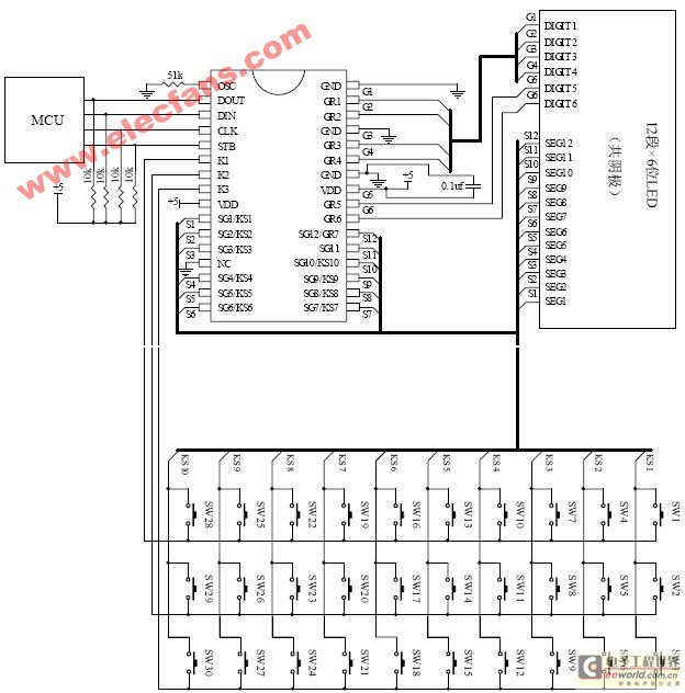
The ET6201 is a LED display control drive circuit with a duty cycle of 1/7 to 1/8. It features 11 segment output gates and 1 segment/gate output, along with a display memory, control circuit, and key scanning circuit, which...
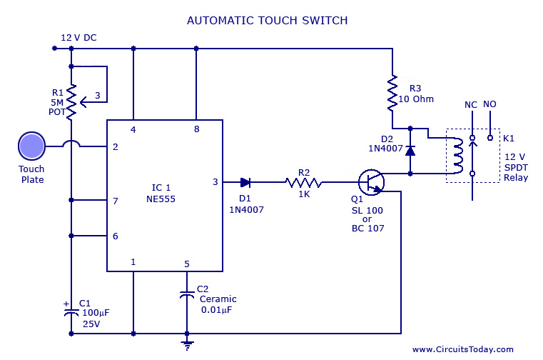
A touch switch circuit schematic utilizing a 555 integrated circuit (IC). When the touch plate is activated, a relay is switched ON for a predetermined duration, which can also be adjusted. The touch switch circuit employs a 555 timer IC...
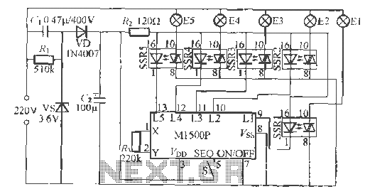
The Shenzhen Skywave Semiconductor Co., Ltd. produces a five-flash integrated circuit controller known as M1500P. This device is manufactured using a DIP 14 standard package and can be customized according to customer specifications for soft seal packaging. It operates...
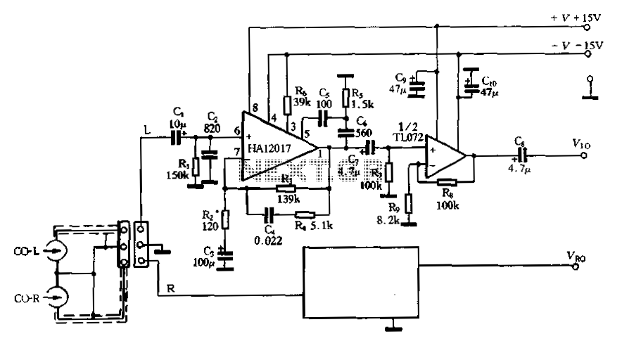
Figure 3-16 illustrates a low-noise preamplifier equalizing circuit using the HA12017. This circuit includes playback components R3, R4, and C4, which conform to a standard balanced network. The gain of the circuit is -7dB at 1kHz, while the output...