
Touch SwitchCircuit using NE 555 IC

The touch switch circuit employs a 555 timer IC configured in monostable mode. In this configuration, the circuit generates a single output pulse when triggered by a touch on the designated touch plate. The touch plate acts as a sensor, detecting the presence of a finger or conductive object, which completes the circuit and triggers the timer.
The key components of the circuit include the 555 timer IC, a relay, a resistor, a capacitor, and the touch plate. The resistor-capacitor (RC) combination determines the duration for which the relay remains activated. By adjusting the resistance or capacitance values, the ON time for the relay can be modified according to the requirements of the application.
Upon activation, the 555 timer outputs a HIGH signal, energizing the relay coil. This action closes the relay contacts, allowing current to flow to the load connected to the relay. After the preset time elapses, the output of the 555 timer returns to LOW, de-energizing the relay and opening the contacts, which disconnects the load.
This touch switch circuit is ideal for applications requiring a simple, user-friendly interface for controlling devices such as lights, fans, or other electrical appliances. The adjustable timing feature enhances its versatility, making it suitable for various scenarios where temporary activation is desired. Proper consideration of component ratings and circuit layout is essential for ensuring reliable operation and safety in the final design.A touch switch circuit schematic using 555 IC.When touched on the touch plate a relay will be switched ON for a preset time. This time can be adjusted too.. 🔗 External reference
Related Circuits

The following method allows the timer to be triggered by a normally closed switch. This would be useful in applications such as intrusion alarms where the protection circuit is broken if a window or door is opened. Trigger Input...
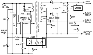
The following figure illustrates an example of a three-output flyback regulator constructed using the LM2577, which features electrical isolation between the input and output voltages. The circuit diagram specifies a voltage of 5V. Electrical isolation between the input and...
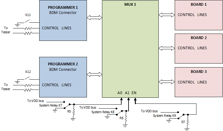
The use of programming pods has become a standard practice in manufacturing, particularly during the early development stages of firmware for new products. Once visual and structural tests are completed, the board is prepared for full functional testing. The...
The schematic diagram below illustrates a basic sample-and-hold circuit utilizing the CA3140 as the readout amplifier for the memory capacitor. The CA3080A is also employed in the design. The sample-and-hold circuit is a crucial component in analog-to-digital conversion systems, allowing...
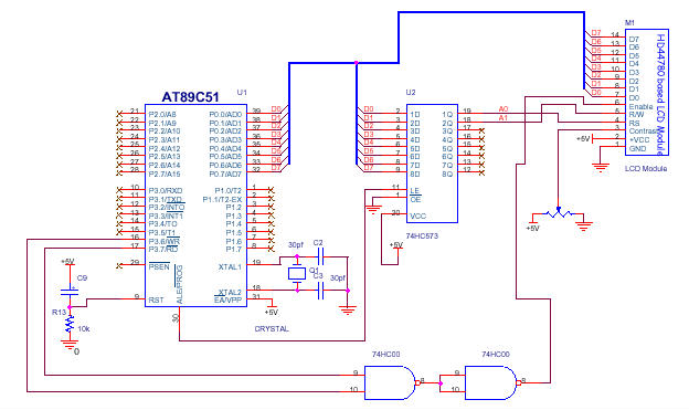
In the circuit presented, the LCD module's Command Register is configured at address 00H and the Data Register at address 01H. Consequently, writing data to address 00H will be interpreted as a command for the LCD, while writing to...
This circuit diagram represents an indicator designed to display a battery voltage of 12 volts. The working principle involves comparing the battery voltage with a reference voltage using the LM324 integrated circuit, which is a low-power quad operational amplifier....