
Circuit 22W Stereo Amplifier Using TDA1554

The 22-watt stereo audio power amplifier circuit based on the TDA1554 is an efficient solution for audio amplification in various applications, including home audio systems and portable speakers. The TDA1554 is a dual power amplifier capable of delivering high-quality audio output while maintaining thermal stability.
The circuit configuration includes essential components such as capacitors for filtering, resistors for setting gain and stability, and the TDA1554 IC itself. The power supply is a critical aspect, requiring a stable 12V source that can provide sufficient current, particularly at peak audio levels. The use of a heatsink is crucial to manage the thermal output of the amplifier, as the device can generate significant heat during operation.
In addition to R1, other passive components in the circuit play vital roles in ensuring optimal performance. Capacitors are typically employed in the power supply section to smooth out voltage fluctuations, while coupling capacitors may be used at the input and output stages to block DC offsets and allow only AC audio signals to pass.
The layout of the circuit should be designed to minimize noise and interference, with careful attention paid to the placement of components and the routing of traces. Grounding practices are also important to ensure that the amplifier operates without hum or buzz, which can degrade audio quality.
Overall, this amplifier circuit represents a straightforward yet effective approach to stereo audio amplification, leveraging the capabilities of the TDA1554 to deliver robust performance in a compact form factor.Here is the 22 watt stereo audio power amplifier circuit diagram based on TDA1554 and integrated circuit from NXP semiconductors (formerly PHILIPS semiconductors). It is very simple and useful circuit for amplify the stereo signals. The circuit dissipates roughly 28 watts of heat, so a good heatsink is necessary. The chip should run cool enough to touch with the proper heatsink installed. the circuit operates at 12 Volts at about 5 Amps at full volume. Lower volumes use less current, and therefore produce less heat. R1 is also a 5% resistor. 🔗 External reference
Related Circuits
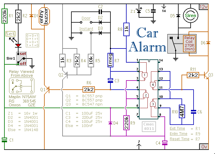
This car alarm circuit includes exit and entry delays, an instant alarm zone, an intermittent siren output, and automatic reset. By incorporating external relays, it is possible to immobilize the vehicle and activate the flashing lights. The car alarm circuit...
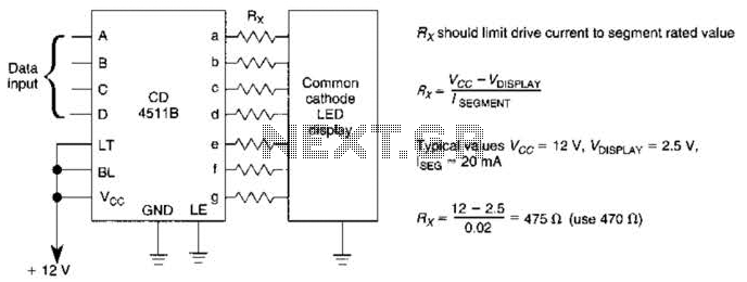
A CD4511B CMOS LED display driver can be utilized to operate a common cathode LED display. Current limiting resistors are employed to restrict the segment current to the specified value at the maximum supply voltage. The CD4511B is a...
This project provides a simple temperature-controlled fan. If the difference between the actual temperature and the user-defined temperature is significant, the fan will operate. The temperature-controlled fan circuit utilizes a temperature sensor, a microcontroller, and a fan motor to regulate...
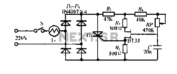
Electrical flow through the saddle j pounds. TV added in a controlled manner Qian Mountain amphipod species lI- ii mi pulsating chord electric. This electric again. The DC Bamboo Division I and the second voltage supply voltage step trigger...
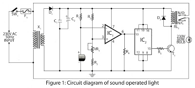
This is a hobby circuit designed for electronics enthusiasts that can turn on and off devices such as lights, fans, and radios in response to the sound of a clap. The sound is detected by a small microphone, which...
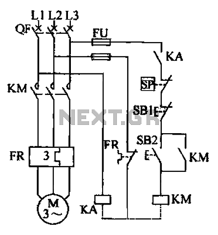
The air compressor control circuit operates based on several key principles. The first function is overload protection, which is facilitated by the thermal relay (FR). In instances of prolonged motor overload, the thermal relay activates to prevent overheating and...