
A Cmos Based Vehicle Anti-Theft Alarm circuit

The car alarm circuit is designed to enhance vehicle security by providing multiple features that deter unauthorized access. The exit and entry delays allow users a predetermined time frame to enter or exit the vehicle without triggering the alarm, thus providing convenience while maintaining security.
The instant alarm zone is a critical feature that activates the alarm immediately upon any unauthorized entry, ensuring that any breach is promptly addressed. The intermittent siren output serves to attract attention without being overly disruptive, making it effective in alerting nearby individuals of a potential theft while minimizing noise pollution.
Automatic reset functionality ensures that the system resets itself after a specified duration, preventing false alarms from remaining active and allowing for normal operation once the vehicle is secured.
Incorporating external relays into the circuit enhances its capabilities significantly. These relays can be utilized to immobilize the vehicle's ignition system, rendering it inoperable without the proper alarm deactivation procedure. Additionally, the ability to flash the vehicle's lights serves as a visual deterrent and alerts the owner or passersby of the alarm status.
The schematic for this circuit typically includes a microcontroller or dedicated alarm IC, various resistors and capacitors for timing functions, and transistors or MOSFETs for driving the siren and relays. The design may also feature input terminals for door sensors, shock sensors, and a key fob receiver for remote control, further enhancing the overall functionality and user experience of the car alarm system.This car alarm circuit features Exit and Entry delays, an instant alarm zone, an intermittent siren output and automatic Reset. By adding external relays you can immobilize the vehicle and flash the lights.. 🔗 External reference
Related Circuits
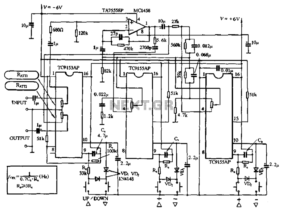
Figure 4-18 illustrates a volume potentiometer T (Xi 153AP) and a tone potentiometer T (155AP) that make up a volume and tone control circuit. This circuit includes Rx and Cx as clock oscillation elements, with values selectable based on...

A static device that couples two circuits to transfer alternating current (AC) from one circuit to another through electromagnetic induction. The current maintains the same frequency but may vary in voltage, phase, or impedance values. A transformer consists of...
The Arduino Uno features an ATMEGA328P-PU microcontroller and various additional components on the board. The objective is to program the microcontroller without relying on the Arduino software, utilizing only the essential components. The goal is to develop projects independently...

The CA3189 integrated circuit (IC) incorporates a symmetrical limiter, a phase demodulator, an audio amplifier, and a logarithmic detector-amplifier. The logarithmic detector-amplifier is particularly noteworthy for enhancing the logarithmic signal meter of shortwave receivers, thereby improving signal reading accuracy....

If familiar with programming languages such as C++, PASCAL, VISUAL BASIC, or DELPHI, it is possible to write a program that sends numbers from 0 to 255 through the parallel port (378 I) of a PC. This process checks...
This circuit provides a visual 9-second delay using 10 LEDs before closing a 12-volt relay. When the reset switch is closed, the 4017 decade counter is reset to the 0 count, illuminating the LED driven from pin 3. The...