
circuit alarm

The circuit design consists of two twin-T oscillators, each configured to produce a distinct audio frequency. The twin-T oscillator circuit is characterized by its ability to generate sine waves with high stability, making it suitable for musical applications. The Q factor is critical in this setup; it must be adjusted to a level that allows the oscillators to produce sound when excited by an external pulse.
The activation of the oscillators is managed by using 555 timer integrated circuits, which are versatile and widely employed in timing applications. The first two 555 timers are configured in monostable mode to generate a pulse for each twin-T oscillator. The duration and timing of these pulses can be fine-tuned to create a harmonious sequence of tones. A third 555 timer can be added to create a repeating sequence, allowing for continuous sound generation.
The outputs of the twin-T oscillators are combined in a mixer circuit, which can be a simple resistor network or a more complex operational amplifier configuration, depending on the desired output characteristics. The mixed signal is then fed into an audio amplifier, which boosts the signal strength to drive a speaker, resulting in audible sound.
For those interested in digital sound synthesis, the mention of Roman Black's one-bit sound algorithm suggests an alternative method for sound generation. This algorithm can produce audio signals using a single bit of data, making it an efficient way to create sounds using microcontrollers. The programming example provided indicates a method for generating sound using a PIC16F628 microcontroller, where the output is handled through a designated output port. The code snippet involves a loop that increments a counter and retrieves corresponding sound data from a lookup table, which is then output through a serial communication interface.
In conclusion, the described circuit is a versatile sound generation system that combines analog and digital techniques to produce a variety of audio outputs. It serves as a foundation for further exploration into sound synthesis and can be adapted for various applications in electronic music and sound design.You can do it with a couple of twin-T oscillators, with the Q set to the edge of oscillation, thus they ring like a bell when kicked with a voltage pulse: Use one Twin-T for each tone, and use something like a pair of 555 timers to generate two pulses to kick each Twin-T in sequence (perhaps a third 555 to repeat the dual-tone sequence). sum the two Twin-T outputs in a mixer and send the mixer output to a audio amp and speaker. This sound circuit (And it is a very sound circuit ) It works so its got to be sound also plays star wars tunes and ding dongs or what ever you want it to play or you could implement Roman blacks one bit sound algorithm Probably will if you know how to use this perhaps you can let some of us know as there are no worked examples or how too`s apart from the recorder which obviosly gives you the required data So if you can do this brilliant maybe you can help some of us out with respect to this Steve We will wait for you to come back with an answer plus example in both C and proton basic Super news at last someone can actually do something quite brilliant You obviously know what bit stream is I`m sure someone that`s as clever as you are will know this So if you know this then how do you output a bit stream via a port in other words how would you actually get a data rate out of a ports pin Steve You can phone a friend, contact the audience or Steve you could take a chance The choice is yours Steve entirely up to you of course Will you Steve be the odd one out 1 2 3 4 5 6 7 8 9 10 11 12 13 14 15 16 17 18 19 20 21 22 23 24 25 26 27 28 29 30 31 32 33 34 35 36 37 38 39 40 41 42 43 44 45 46 47 48 49 50 51 52 53 54 55 56 57 58 59 60 61 62 63 64 65 66 67 68 69 70 71 72 73 74 75 76 77 78 79 80 81 82 83 84 85 86 87 88 89 90 91 92 93 94 95 96 97 98 99 100 101 102 103 104 105 106 107 108 109 110 111 112 113 114 115 116 117 118 119 120 121 122 123 124 125 126 127 128 129 130 131 132 133 134 135 136 137 138 139 140 141 142 143 144 145 146 147 148 149 150 151 152 153 154 155 156 157 158 159 160 161 162 163 164 165 166 167 168 169 170 171 172 173 DEVICE 16F628 `OUTPUT PORTB. 0 bitline DIM W AS BYTE `For working register DIM COUNTER AS BYTE `Counter DIM MUSIC AS BYTE `W for music bytes W = 0 COUNTER = 0 convert: COUNTER = COUNTER + 1 `counter + =1 IF COUNTER = 120 THEN `Finish end of the cycle program GOTO complete ENDIF MOVF COUNTER, 0 ` CALL TABLO `Call Table 0 MOVWF MUSIC SEROUT PORTB.
0, 600, [MUSIC] pause 1 GOTO convert TABLO: ADDWF PCL, 1 `Increment PC counter by one ;- 0 retlw 101010 ; aa retlw 101010 ; aa retlw 100101 ; a5 retlw 100101 ; a5 retlw 011001 ; 99 retlw 010110 ; 96 retlw 100101 ; a5 retlw 100100 ; 64 ;- 8 retlw 111010 ; ba retlw 001101 ; 8d retlw 010010 ; 92 retlw 001011 ; cb retlw 101100 ; 2c retlw 001001 ; c9 retlw 101001 ; a9 retlw 011010 ; 5a ;- 16 retlw 100110 ; 66 retlw 100101 ; a5 retlw 011001 ; 59 retlw 010101 ; 95 retlw 001011 ; 8b retlw 001100 ; 4c retlw 010110 ; d6 retlw 101101 ; 2d ;- 24 retlw 110011 ; 33 retlw 010001 ; 51 retlw 101100 ; 6c retlw 001101 ; cd retlw 000111 ; 47 retlw 110110 ; 36 retlw 110101 ; 35 retlw 011100 ; 1c ;-%- 32 retlw 111000 ; b8 retlw 101100 ; ac retlw 110010 ; 72 retlw 100010 ; e2 retlw 110001 ; b1 retlw 010011 ; d3 retlw 001010 ; 8a retlw 001010 ; ca ;-%- 40 retlw 001110 ; ce retlw 101011 ; 2b retlw 110011 ; 33 retlw 101001 ; 69 retlw 001100 ; 4c retlw 001101 ; cd retlw 100101 ; a5 retlw 110101 ; 35 ;-%- 48 retlw 101110 ; 2e retlw 010100 ; 94 retlw 010101 ; d5 retlw 011010 ; 9a retlw 010110 ; 56 retlw 100101 ; 65 retlw 101001 ; a9 retlw 011010 ; 5a ;- 56 retlw 010110 ; 96 retlw 001001 ; c9 retlw 101010 ; 6a retlw 011011 ; 5b retlw 101001 ; 29 retlw 010010 ; d2 retlw 101100 ; 6c retlw 100111 ; a7 ;-%- 64 retlw 001011 ; 4b retlw 110010 ; 32 retlw 111001 ; b9 retlw 101100 ; 2c retlw 001010 ; ca retlw 101001 ; e9 retlw 110011 ; 33 retlw 101011 ; 2b ;-%- 72 retlw 100100 ; a4 retlw 001101 ; cd retlw 0011 🔗 External reference
Related Circuits
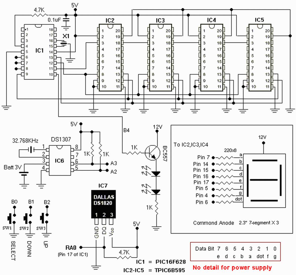
The clock is based on the PIC16F877 microcontroller from Microchip Technology Inc., which performs all of the logic necessary to decode the MSF signal and display the time on twelve 7-segment displays. The circuit design incorporates the PIC16F877 microcontroller, a...
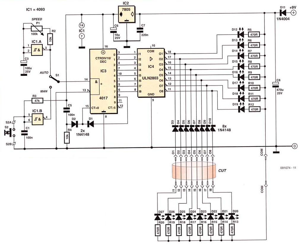
This network wiring tester consists of two components: a transmitter unit, which is powered and installed at the network's starting point, and a passive receiver unit that can be moved from socket to socket. Both units contain eight LEDs,...
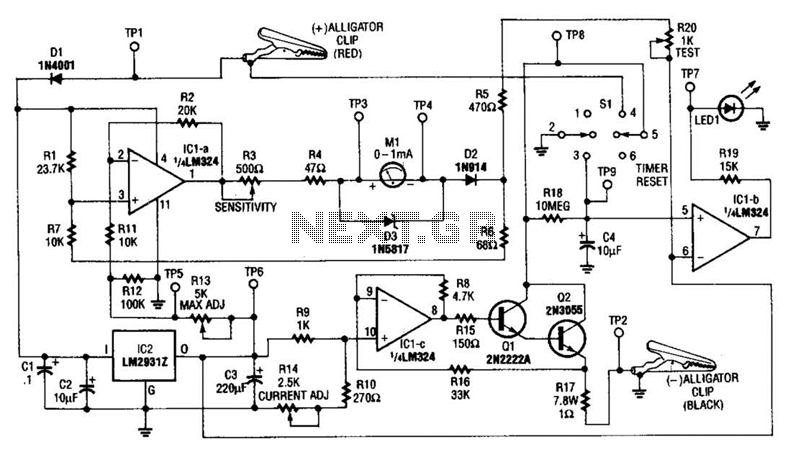
This circuit measures the cold cranking amps of a battery by discharging the surface charge and then assessing the internal resistance. This method provides a more accurate measurement than merely observing the instantaneous voltage drop under load. A constant-current...
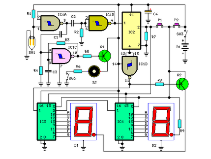
This circuit measures the distance covered during a walk. The hardware is housed in a small box that can be placed in a pocket, and the display is designed as follows: the leftmost display D2 (the most significant digit)...

The 555 timer integrated circuit (IC) is an exceptionally versatile component utilized in various applications, including generating clock pulses, switch debouncing, and functioning as an output transducer. The standard 555 IC is packaged in an 8-pin configuration, available in...
The following circuit illustrates a Repeating Interval Timer Circuit Diagram. This circuit is based on the CMOS 4060 integrated circuit (IC). Features include a 6-pin output. The Repeating Interval Timer Circuit utilizing the CMOS 4060 IC is designed to generate...