
Circuit Diagram Based On The 555 Timer IC

The astable circuit utilizing the 555 Timer IC operates in a continuous oscillation mode, generating a square wave output without requiring any external triggering. This configuration is particularly useful in applications such as flashing lights, tone generation, and pulse width modulation.
In this circuit, the 555 Timer is configured in astable mode, which means it alternates between its high and low states. The frequency of oscillation is determined by the resistor and capacitor values connected to the timer. Specifically, two resistors (R1 and R2) and one capacitor (C1) are used to set the timing intervals. The relationship between these components can be described by the formula:
\[ f = \frac{1.44}{(R1 + 2R2) \cdot C1} \]
where \( f \) is the frequency of the output pulse. The duty cycle, or the mark-space ratio, is influenced by the resistor values as well, which can be adjusted to achieve the desired output characteristics.
The output of the 555 Timer is typically taken from pin 3, which can drive loads directly or be interfaced with other circuits. The diode in the circuit may be used for protection against back EMF if inductive loads are connected, ensuring the longevity of the components.
Overall, this astable circuit provides a simple yet effective solution for generating square wave signals, demonstrating the versatility of the 555 Timer IC in practical electronics applications. It is important to select the appropriate component values to achieve the desired frequency and duty cycle for specific use cases.The following circuit shows about Practical Electronics/Plugins/Astable Circuit Diagram. This circuit based on the 555 Timer IC. Features: gives a pulse of about 2Hz with a very low mark-space ratio, used for any number of things, single 555 Astable, plugin is very versatile. Component: IC, Resistor, Diode, Capacitor. [ en. labs. wikime dia. org ] 🔗 External reference
Related Circuits
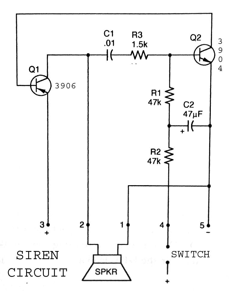
3904 3906 Siren Circuit. The circuit generates a wailing siren sound when the switch is activated. The 3904 3906 Siren Circuit is designed to produce a distinctive wailing sound, commonly used in alarm systems and signaling devices. The circuit utilizes...

This is a versatile voice modulator circuit utilizing the HT8950A IC from Holtek Semiconductors. The IC can generate seven upward or downward frequency steps based on the input voice at a rate of 8 Hz. Additionally, it features two...

This is the circuit diagram of a touch-activated alarm system that remains operational during power outages. The alarm system is triggered when someone touches the designated touch plate. A notable feature of this circuit is the automatic battery activator,...

Narrow Band Frequency Modulation (NBFM) is utilized in this 27 MHz transmitter circuit schematic. This circuit is based on the Motorola MC2833 VHF transmitter, which integrates FM modulation and narrow band capabilities into a single chip. P1 is designated...

The 1B32 application circuit features multiple pressure sensors as illustrated in the figure. Excitation power is supplied through the AD542, which is followed by a TIP32 transistor that drives multiple bridge sensors. The AD542 operates as a Bi-FET in...

This second-order filter, designed for audio applications, utilizes an LM1458 or a similar operational amplifier. It is tunable with a cutoff frequency ranging from 30 Hz to 300 Hz. The resistors R2a and R2b are ganged log-taper potentiometers. The described...