
Circuit Diagram of a Crystal Radio Receiver with AF Amplification using a Germanium Transistor
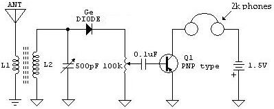
The Crystal Radio Receiver Circuit is a simple yet effective design that operates without the need for an external power source, relying instead on the energy harvested from radio waves. The core components of this circuit include an antenna, a diode, a tuning capacitor, and a Germanium transistor for amplification.
The antenna captures radio frequency signals, which are then rectified by the diode. In this circuit, a Germanium diode is typically used due to its low forward voltage drop, allowing for efficient rectification of weak signals. The output from the diode is a modulated audio signal, which is then passed through a tuning capacitor. This capacitor, in conjunction with an inductor (not explicitly mentioned in the description but commonly used), forms a resonant circuit that allows the user to select specific radio frequencies.
After rectification and tuning, the audio signal is weak and requires amplification for practical listening. A Germanium transistor is employed in the AF amplification stage due to its favorable characteristics for low-frequency audio applications. The transistor is configured in a common-emitter configuration, providing voltage gain and current amplification. Proper biasing of the transistor is crucial to ensure it operates in the active region, allowing for linear amplification of the audio signal.
The output of the transistor can be connected to a speaker or headphones, enabling audible sound reproduction of the received radio signals. Additionally, capacitors may be used for coupling and bypassing to enhance the performance of the amplifier stage, ensuring that only the desired audio frequencies are amplified while minimizing noise.
This schematic exemplifies a practical application of basic electronic components in creating a functional radio receiver, demonstrating the principles of radio wave reception, signal rectification, and audio amplification.The following schematic shows a Crystal Radio Receiver Circuit Diagram with AF Amplification using a Germanium Transistor. The addition of AF amplification will.. 🔗 External reference
Related Circuits
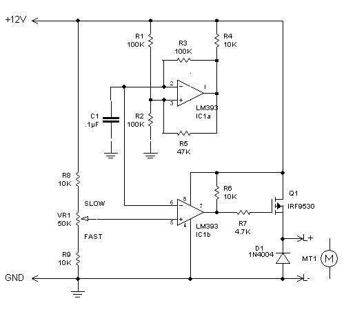
The inquiry pertains to identifying the component within the circuit that regulates the minimum RPM achievable. The current operational range of the motor is between 1400 and 3700 RPM, and there is an interest in modifying the circuit to...

The schematic illustrates the design of a circuit that measures the resistance of the skin and transforms it into a functional switching signal. This circuit typically employs a resistive sensor, often referred to as a skin resistance sensor or galvanic...

Most consumer electronic devices utilize infrared remote controls for convenient operation. The carrier frequency of these remote controls typically ranges from 36 kHz to 38 kHz. Control codes are transmitted to the device's receiver in a serial format, which...
The automatic sprinkler controller circuit consists of a clock timing controller, a monostable flip-flop, a bistable flip-flop, an electronic switch, a self-excited multivibrator, a counter, a solenoid valve control circuit, and a power supply circuit. The power supply circuit...
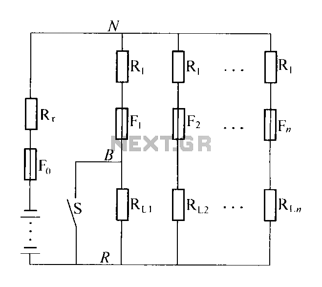
The circuit diagram illustrates a high-impedance distribution system characterized by low resistivity distribution. A notable feature is the series resistance of the shunt load current limiting resistor R1, typically valued at five to ten times the internal resistance of...
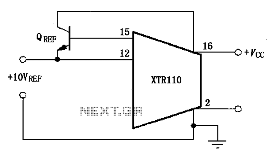
The XTR110 features an internal voltage reference that can output a current of 10mA. By incorporating an external NPN transistor, designated as QREF, the output current capability can be increased. When the VCC voltage reaches 40V, a 2N3055 transistor...