
Circuit Diagram of Fan Speed Control With NE5560 IC

The circuit for a constant speed motor control typically employs feedback mechanisms to maintain a stable output speed. This can be achieved using a closed-loop control system, which includes components such as a microcontroller, sensors, and a driver circuit.
The microcontroller serves as the central processing unit, receiving input from sensors that monitor the motor's speed and load conditions. Commonly used sensors include tachometers or encoders, which provide real-time data on the motor's rotational speed.
The driver circuit, often consisting of a MOSFET or an H-bridge, regulates the power supplied to the motor based on the microcontroller's commands. This allows for precise adjustments to the voltage and current supplied to the motor, compensating for any changes in load or supply voltage.
Additionally, the use of PID (Proportional-Integral-Derivative) control algorithms can enhance the performance of the system. The PID controller calculates the error between the desired speed and the actual speed, adjusting the output to minimize this error over time.
Incorporating these elements into the design results in a robust motor control system capable of maintaining a consistent speed under varying operational conditions, thereby improving the overall efficiency and reliability of motor-driven applications.useful to make a constant speed motor control. Which means the speed will stay constant despite of load and electric voltage change. Component: . 🔗 External reference
Related Circuits
.png)
Gratitude is extended for the manual that was purchased; it is as described, enabling the continuation of work on the TV. The service will be utilized for all future manual needs. Thank you once again. Best regards, Lazlo. Most...
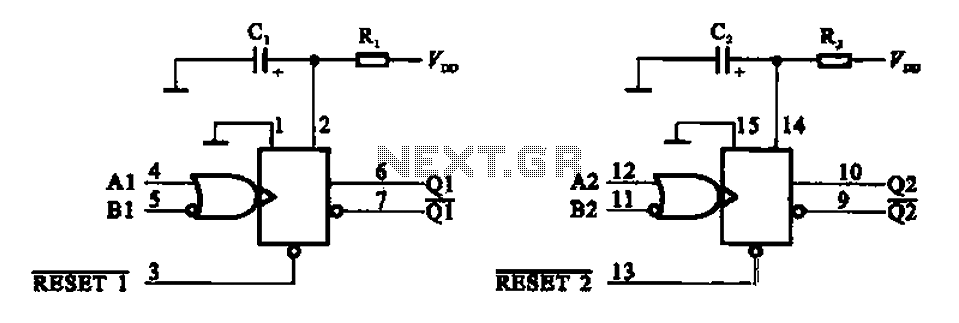
A functional block diagram of the MC1428 Monoflop illustrates the features of the integrated circuit MC14528. This IC includes two monostable trigger circuits, making it more convenient to use. The MC14528 is a versatile integrated circuit designed for monostable applications,...
The circuit described can connect two telephones in parallel and function as a two-line intercom. Typically, a single telephone is connected to a telephone line. When another telephone is needed at a distance, a parallel line is utilized for...
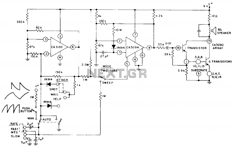
The circuit utilizes a CA3130 BiMOS operational amplifier configured as a multivibrator to regulate the siren's frequency. A CA3094 is employed as a voltage-controlled oscillator (VCO), which is subsequently connected to a CA3082 transistor array that drives a speaker....
Colour sensor is an interesting project for hobbyists. The circuit can sense eight colours, i.e. blue, green and red (primary colours); magenta, yellow and cyan (secondary colours); and black and white. The circuit is based on the fundamentals of...
Dodge Durango Fog Light Wiring Diagram. The Dodge Durango fog light wiring diagram provides a visual representation of the electrical connections and components involved in the fog light system of the vehicle. This diagram typically includes the battery, fog light...