
Siren system circuit

The circuit design incorporates several key components that work together to achieve the desired functionality of the siren system. The CA3130 BiMOS op-amp serves as the core of the multivibrator configuration, providing the necessary gain and stability for generating square wave signals. This output signal directly influences the siren's rate, allowing for adjustable frequency modulation based on user input.
The CA3094 voltage-controlled oscillator (VCO) is crucial for creating variable frequency outputs. It receives control voltage inputs that determine the oscillation frequency, which can be modulated by the user through the "Rate" switch. This feature allows for customization of the siren's sound pattern, enhancing its effectiveness in various applications.
The CA3082 transistor array functions as a driver stage, amplifying the signal from the VCO to a level sufficient to drive the speaker. This component ensures that the audio output is loud and clear, making the siren more effective in alerting or warning scenarios.
The inclusion of a "Manual" or "Auto" mode switch provides flexibility in operation. In "Manual" mode, the siren can be set to produce sound intermittently, while "Auto" mode allows for continuous sound output. This dual functionality is particularly useful in situations where different alerting patterns may be required.
Furthermore, the additional three switches—designated for "Mode," "Attack," and "Rate"—offer further control over the siren's performance. The "Mode" switch may allow for different sound patterns or tones, the "Attack" switch could control the ramp-up time of the sound, and the "Rate" switch adjusts the frequency of the oscillation, providing a comprehensive user interface for tailoring the siren's operation to specific needs.
Overall, this circuit design exemplifies a well-thought-out approach to creating a versatile siren system capable of meeting diverse operational requirements.The circuit uses a CA3130 BiMOS op amp as a multivibrator to control the siren's rate. A CA3094 used as a VCO is followed by a CA3082 transistor array used to drive a speaker. A "Manual" or "Auto" mode switch allows the user to select either intermittent or continuous siren operation, respectively. In addition, three switches are available that control "Mode", "Attack", and "Rate".
Related Circuits
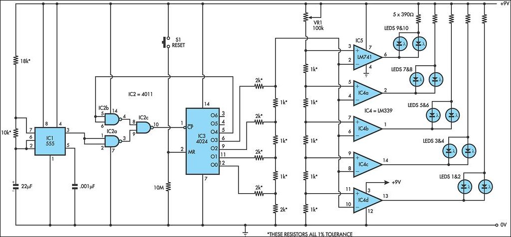
This LED circuit replicates the initial LED sequence currently utilized by FISA for Formula One racing. It can also be employed with slot car sets, such as HO scale AFX, Life Like, or Tyco sets, or used in communication-controlled...

Here is a design circuit for a frequency modulator that is equipped with a tuning circuit. In this circuit, a pair of 1N4007 diodes is utilized as varactor diodes. The choice of 1N4007 diodes is not due to their...

This is a simple automatic light switch circuit designed for bedrooms. After construction, the input terminals of this circuit should be connected in parallel to the intended lighting fixture. The automatic light switch circuit utilizes a light-dependent resistor (LDR) as...
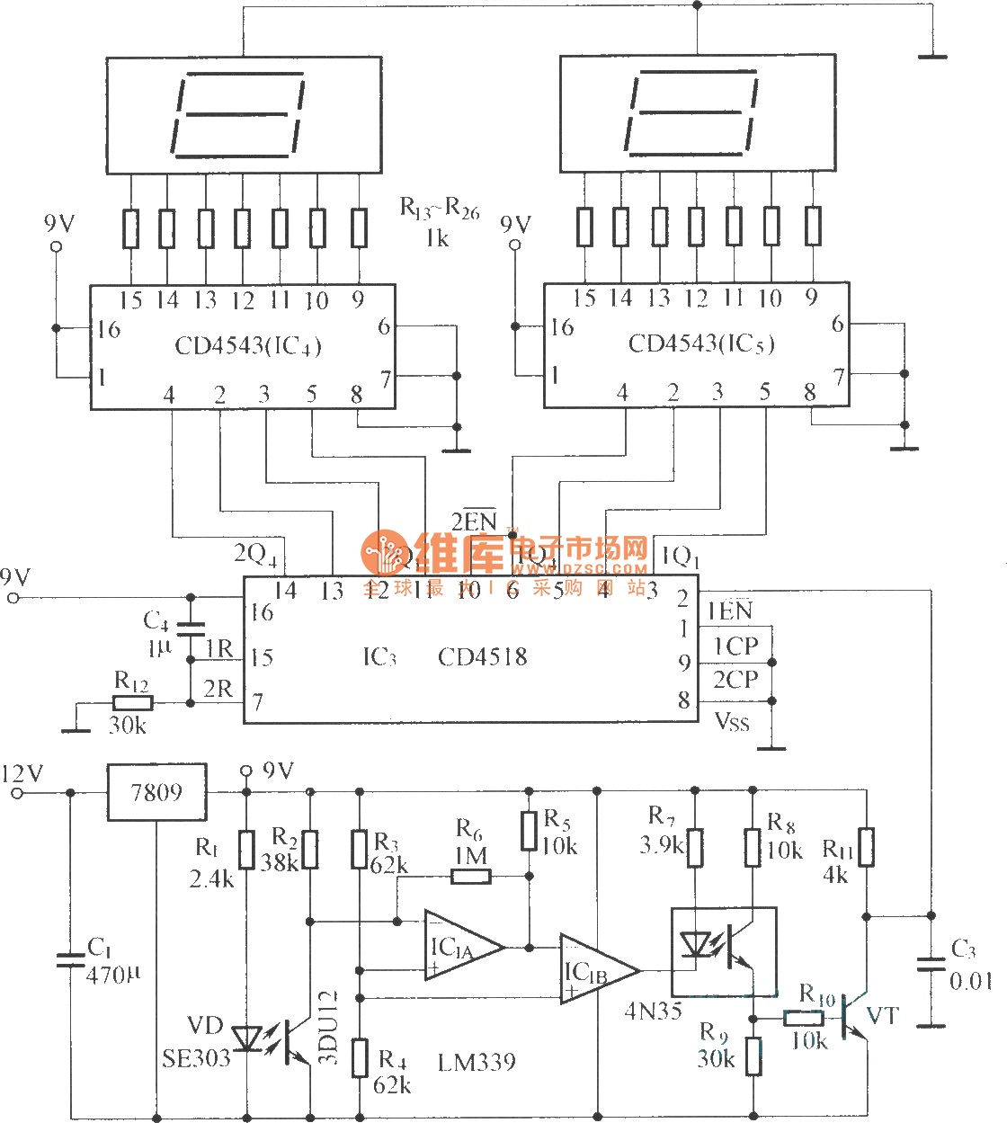
The circuit includes an optical input circuit (VD, 3DU12), a pulse forming circuit (IC1A, IC1B functioning as a voltage comparator; optical coupler; transistor switching circuit), and a counting and display circuit. The circuit architecture consists of several key components that...
This is a differentiator circuit. This circuit can be used to perform differential operations. There are two types of differentiators: the true differentiator and another type. A differentiator circuit is designed to output a voltage that is proportional to the...
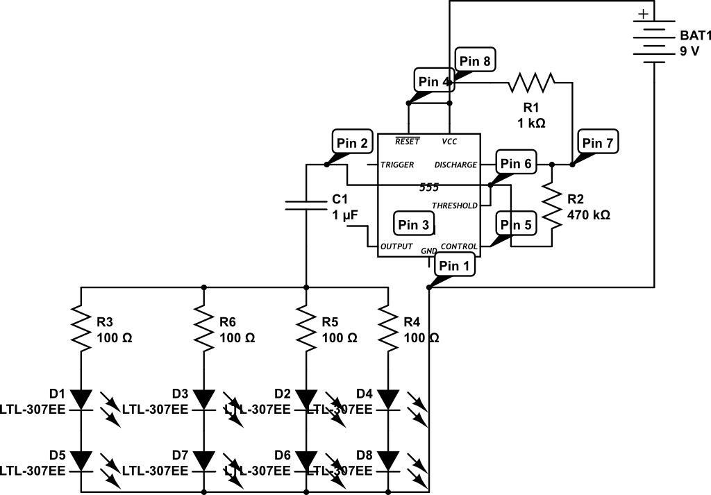
LEDs are rated for a continuous current of only 30 mA, while this circuit operates them at approximately 50 mA. Although this is acceptable for low duty cycles with short pulses, the intended design has a high duty cycle....