
Circuit DIY of the inverter (picture and text is explained in detail)
")
The inverter circuit operates on the principle of converting direct current (DC) from a battery into alternating current (AC) using the MOS field-effect transistor and transformer combination. The MOSFET acts as a switch that rapidly turns on and off, creating a square wave output. This square wave is effective in driving the transformer, which then steps up the voltage to the desired level.
The CD4069 inverters are configured in such a way that they provide the necessary gain and shape to the square wave signal. The compensating resistor R1 is critical for maintaining the stability of the oscillation frequency, especially under varying load conditions. Capacitor C1 plays a significant role in determining the oscillation period, thus influencing the frequency of the output waveform.
The use of a low-resistance 12V car battery is essential for providing sufficient current for the inverter to function effectively, especially under load conditions. The testing with an electric lamp allows for practical observation of the inverter's performance, demonstrating how the output voltage and power consumption relate to changes in load.
The inverter's design emphasizes simplicity and efficiency, making it a practical solution for applications such as electronic fans, where reliable and adjustable AC power is required. The ability to produce a stable output voltage from a variable input source is a notable feature of this inverter design, contributing to its versatility in various electronic applications.Inverter of what this text produces see Fig. 1 Mainly by the MOS field effect tube, the ordinary power transformer forms. Its output power depends on the power of MOS field effect tube and power transformer, avoid the convoluted voltage transformer to wind, suit electronic fan`s spare time to adopt while making. Now introduce operating principle and fabrication process of this inverter. Adopt six inverters of CD4069 and form the signal generator of rectangular wave here. R1 is the compensating resistance in the circuit, used for improving the oscillating frequency caused by change of the mains voltage unstably. The vibration of the circuit charged and discharged to finish through the electric capacity C1. Its oscillating frequency is f =The maximum frequency of 1/2. 2 of the RC. diagramatic circuit is: fmax=1/2. 2* 3. 3* 103* 2. 2* 10-6=62. 6Hz; Minimum frequency fmin =1/2. 2* 4. 3* 103* 2. 2* 10-6=48. 0Hz. is because of the error of the component, actual value will have some the difference. Other surplus inverters, earth and avoid influencing other circuit in the input end. Because the maximum crest of signal voltage of vibration that the rectangular wave signal generator outputs is 0~5V, for drive the intersection of power and switching circuit fully, here show as in Fig.
3 from voltage amplification to 0~12 V. oscillating beacon with TR1, TR2. The test circuit is shown in Fig. 4. The input power used for test here adopts internal resistance low, with big discharge current generally greater than 100A 12V car storage battery, can offer for circuit the ones sufficient input power. Test is used and supported for the ordinary electric lamp. The method to test is to pass and change load magnitude, and the measurement input current, voltage and output voltage at this moment.
The output voltage drops with increase of load, the consumed power of the bulb changes with voltage change. We can find out the relation between output voltage and power through calculating too. But will be with adding and changes in the voltage change of both ends because of the resistance of the electric lamp in fact, and the output voltage, electric current are not the sine wave, so the calculation of this kind can only be regarded as and estimated.
Regard supporting the example as the electric lamp of 60W as: Suppose the resistance of the bulb does not change with voltage change. Because of R light =V2/ W=2102/60=735, so when the voltage is 208V, W=V2/R=2082/735 =Therefore 58. 9 W. can convert the relation between voltage and power out. Pass The Test, we find when the output power is about 100W, the input current is 10 A. the output voltage is 200V at this moment. 🔗 External reference
Related Circuits
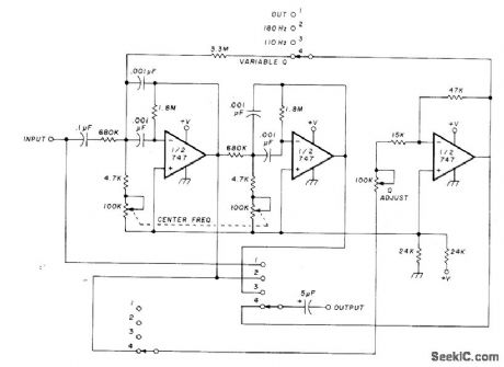
The circuit utilizing Optical Electronics 9803 operational amplifiers separates an audio frequency (AF) input signal into two outputs. The low-pass output allows frequencies from DC up to 10 Hz, while the high-pass output encompasses frequency content above 10 Hz,...
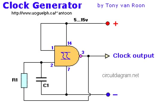
The following diagram is the clock generator circuit diagram built using NAND gate logic integrated circuits (ICs). The circuit can utilize either the IC 7400, which is a TTL type, or the IC 4011, which is a CMOS type....
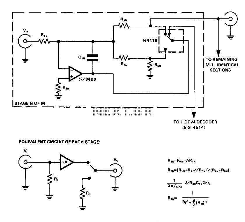
CMOS switches are utilized to select entries in audio circuits. While these switches can introduce unacceptable levels of distortion, incorporating them into the feedback network of an operational amplifier (op amp) can effectively minimize this distortion. The circuit employs...

The LT6552 is a video difference amplifier optimized for low voltage single supply operation. The LT6552 features a 75MHz 3dB bandwidth, a 600V/µs slew rate, and ±70mA output current, making it ideal for driving cables directly. This circuit maps...
The circuit diagram for a dynamic toy that produces eight sounds and five flashing lights is illustrated. It features the HFC3018 module, capable of generating eight distinct sounds, including step gunfire, aviation gunfire, game sight, telephone sight, bomb 1,...
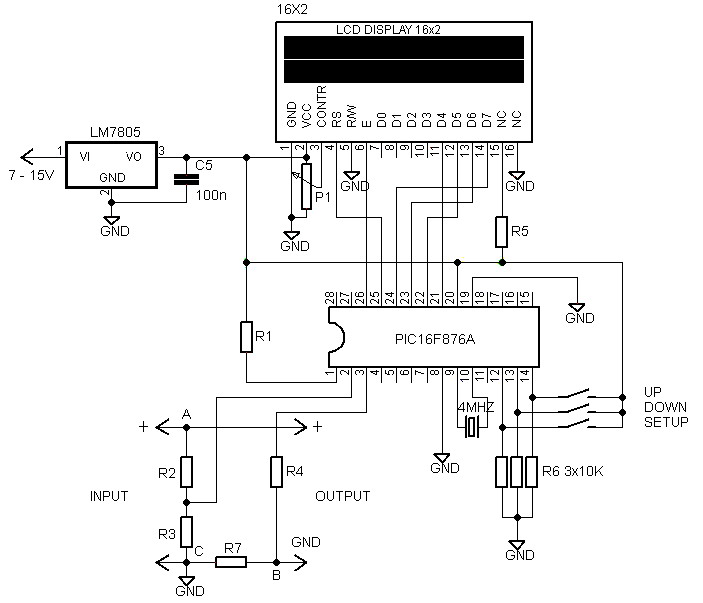
A voltmeter and ammeter using a PIC microcontroller can measure voltage and current simultaneously. This setup employs a PIC16F876A as the data processor for voltage and current measurements. An LCD display (16x2) is utilized to present the measured voltage...