
pic volt and amere meter circuits

The voltmeter and ammeter circuit utilizing the PIC16F876A microcontroller is designed for simultaneous measurement of voltage and current. The microcontroller serves as the central processing unit, collecting data from the measurement sensors and processing it for display. The choice of the PIC16F876A is due to its capability to handle analog-to-digital conversion, making it suitable for accurate voltage and current readings.
The circuit architecture includes a voltage divider for voltage measurement and a shunt resistor for current measurement. The voltage divider scales down the input voltage to a range that can be safely read by the microcontroller's analog input pins. The shunt resistor, placed in series with the load, allows for current measurement by producing a voltage drop proportional to the current flowing through it. The microcontroller reads this voltage drop, applies Ohm's law, and calculates the current.
An LCD module, specifically a 16x2 display, is integrated into the circuit to provide a user-friendly interface for displaying the measured values. The display is connected to the microcontroller via an I2C or parallel interface, depending on the configuration chosen. This allows for real-time monitoring of voltage and current, enhancing usability in various applications.
Calibration is an essential aspect of this circuit, ensuring accurate measurements. The inclusion of three buttons facilitates user interaction for calibration purposes. These buttons can be programmed to set reference points or adjust the display for specific ranges, allowing for fine-tuning of the measurements based on user requirements.
The entire circuit operates on a 5V DC power supply, which is a common voltage level for microcontroller applications. This choice of power supply ensures that the circuit is compatible with a wide range of components and simplifies integration into existing systems.
Overall, the voltmeter and ammeter circuit with the PIC16F876A microcontroller offers a robust solution for simultaneous voltage and current measurement, with an emphasis on accuracy, ease of use, and flexibility through calibration options.Volt meter and ampere meter with PIC can be used to measure voltage and current at the same time. The series of volt meter and ampere meter with PIC uses a PIC16F876A as a data processor voltage and current are measured. This circuit uses a LCD viewer 16 G— 2, which is used for displaying data voltage and current measurements.
In the article voltmeter and ampere meter with PIC is to be discussed is limited to devices faucet only. For more details can be seen from the image sequence volt meter and ampere meter with PIC below. In the circuit volt meter and ampere meter with PIC above used 3 pieces of buttons for setting Calibration measurement data. The circuit is basically working with the source voltage 5VDC. 🔗 External reference
Related Circuits
This circuit is an adjustable voltage reference circuit, which serves as a voltage source that provides a voltage greater than that of the reference diode. High precision applications that operate over an extended temperature range necessitate a restriction on...
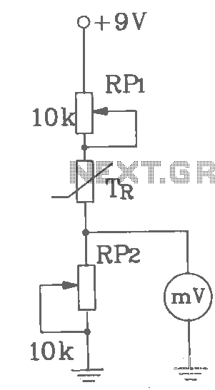
T-121 temperature sensor electronic thermometer circuit diagram shown below The T-121 temperature sensor circuit is designed to measure and display temperature readings accurately. The circuit typically consists of a temperature sensor, such as the T-121, which converts temperature variations into...
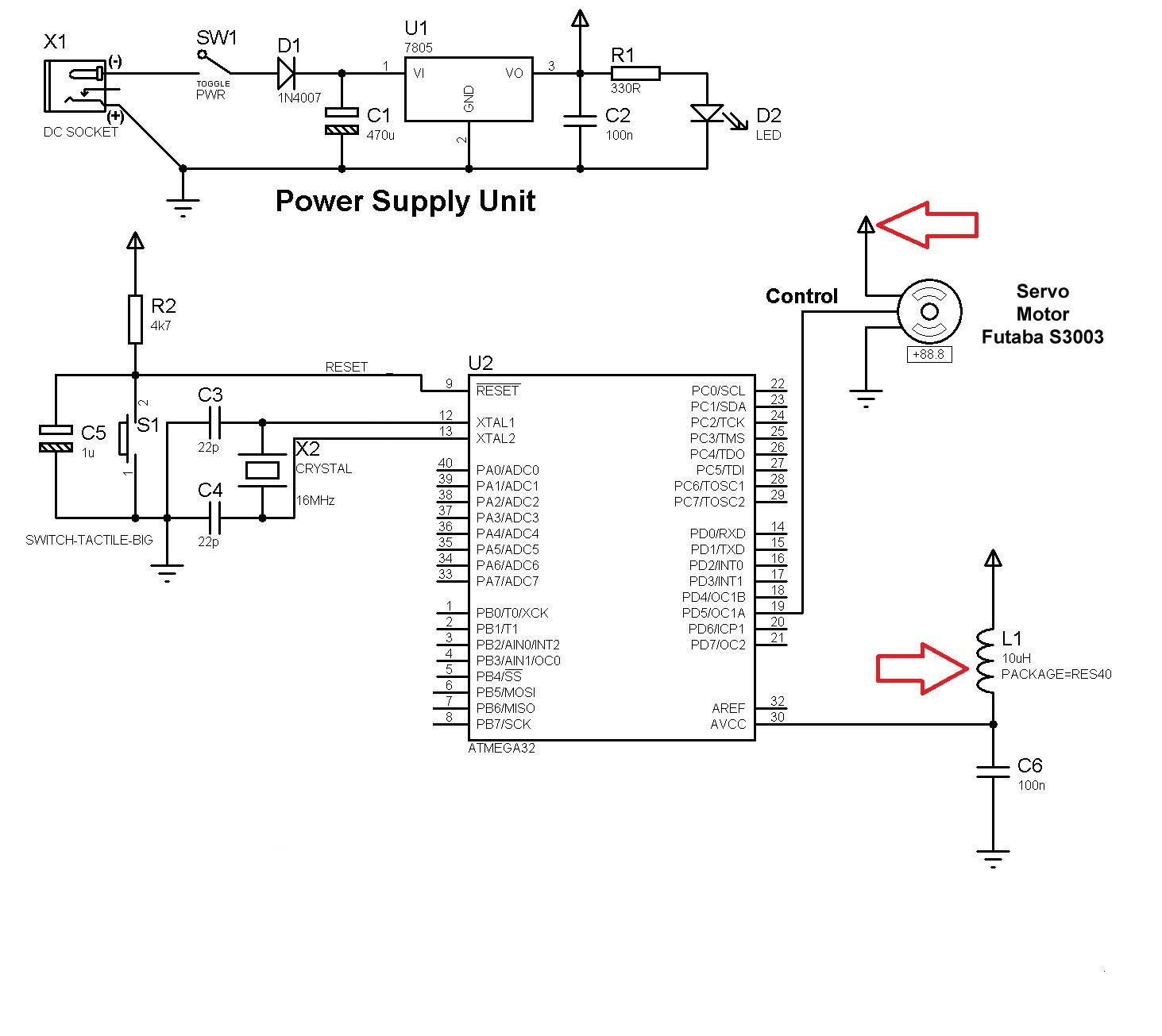
Good preparation. There is one suggestion to use RFM70 or RFM22 for RF communication. The RFM70 and RFM22 are low-power, high-performance RF transceiver modules designed for wireless communication applications. Both modules operate in the 2.4 GHz ISM band, making them...
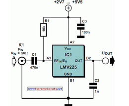
The National Semiconductor LMV225 is a linear RF power meter integrated circuit (IC) in a surface-mount device (SMD) package. It operates over a frequency range of 450 MHz to 2000 MHz. The LMV225 is designed for precise measurement of radio...
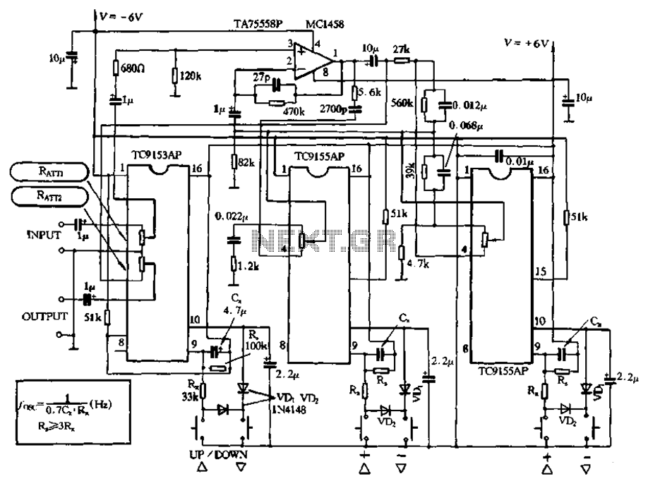
Figure 4-18 illustrates a volume potentiometer T (Xi 153AP) and a tone potentiometer T (155AP) that make up a volume and tone control circuit. This circuit includes Rx and Cx as clock oscillation elements, with values selectable based on...
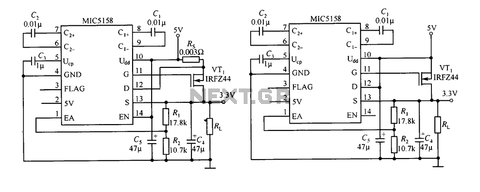
The circuit consists of peripheral components for the MIC5158, a linear regulator that converts a 5V input into a 3.3V output with a maximum current of 10A. When the input voltage (Ui) is 5V, an N-channel MOSFET, specifically the...