
Circuit for controlling 8 appliances using TV Remote

This infrared control circuit operates by receiving commands from a standard TV remote through the TSOP 1738 receiver. The receiver captures the modulated infrared signals and converts them into a digital format that can be processed by the AT89S52 microcontroller. The microcontroller is programmed to recognize specific key presses from the remote, corresponding to the control of different devices.
Each device is connected to the circuit via relays that are activated by the ULN2803 buffer. This component serves as an intermediary, allowing the microcontroller to control high-power devices without exceeding its output current limitations. The ULN2803 consists of multiple Darlington pairs, providing sufficient current amplification to energize the relays, which in turn switch the connected devices on or off.
The schematic layout includes the TSOP 1738 positioned to receive infrared signals unobstructed, with its output connected to one of the input pins of the AT89S52. The microcontroller is programmed to decode the received signals and determine which device to activate based on the key pressed on the remote. The outputs from the microcontroller are connected to the ULN2803 inputs, which are then connected to the relay coils. Each relay is wired to a specific device, ensuring that when a corresponding key is pressed, the correct relay is energized, allowing control over the connected devices.
Overall, this circuit design provides a versatile solution for controlling multiple devices with a single remote, leveraging the capabilities of the AT89S52 microcontroller, the TSOP 1738 infrared receiver, and the ULN2803 relay driver.The IR circuit can be used to switch devices using TV Remote. Normal circuits can switch only one device. But using this circuit, different devices can be controlled using same remote with different switches. In this circuit, we interfaced 8 devices. These devices are switched using remote keypad -1 to 8. AT89S52 microcontroller is used to control the inputs and outputs. TSOP 1738 (infrared receiver) is used to receive the infrared signals from TV Remote. ULN2803 (High voltage, high current) buffer is used to drive relays. 🔗 External reference
Related Circuits
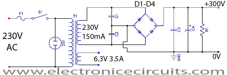
This project is a successful vacuum tube amplifier utilizing a 6V6GT output pentode configured in triode mode, producing approximately 4.5 watts of output power. The design features a single-ended audio amplifier with a resistive input network, a driver stage,...
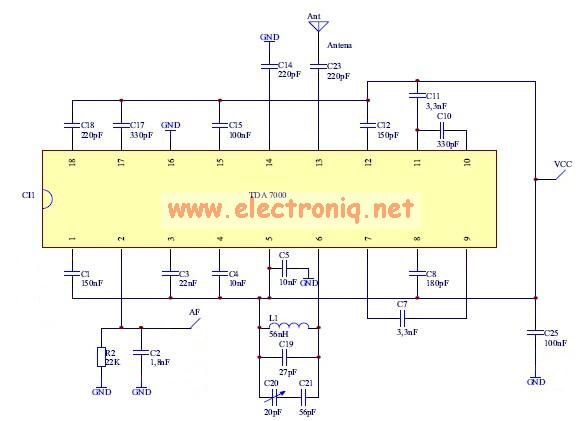
The TDA7000 features a Frequency-Locked-Loop (FLL) system with an intermediate frequency of 70 kHz, and selectivity is achieved through active RC filters. The only calibration required is for the resonant circuit associated with the oscillator, which is necessary for...
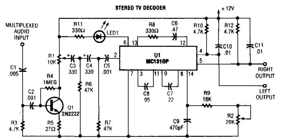
A simple stereo TV decoder circuit built with the MC1310P. Transistor Q1 functions as an audio amplifier, while U1 operates at a 31.5 kHz subcarrier frequency, which is similar to a 38 kHz FM multiplex. The pilot frequency is...
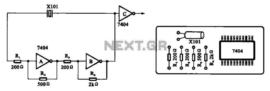
A clock oscillator is commonly utilized in digital signal processing circuits and microprocessor circuits. Digital signal transmission and signal processors necessitate a clock, which serves as the system's timing signal, while the data signal functions as a synchronization signal....
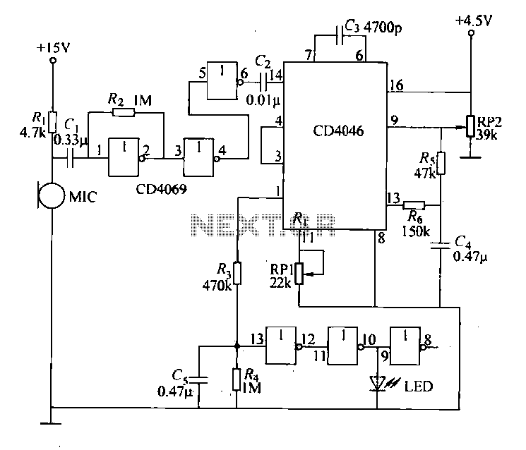
Each issue produces a specific frequency of sound, and the audio remote control will switch states based on these frequencies. The circuit is designed to detect other frequencies emitted by environmental sounds with strong anti-interference capabilities. The circuit operates...
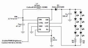
The schematic diagrams for the TPS61042 current LED driver illustrate its capability to power eight LEDs with an efficiency of 81% at 3.6V and 18.6mA. The TPS61042 is commonly utilized in applications such as white LED supply for backlight...