
Circuit forms constant-current SCR

The silicon-controlled rectifier (SCR) is a semiconductor device that functions as a switch, allowing control over high voltage and high current applications. It is composed of four layers of alternating p-type and n-type materials, forming a structure that can be triggered into a conductive state by applying a gate current. The SCR remains in this conductive state until the current flowing through it falls below a certain threshold, known as the holding current.
In practical applications, the SCR is commonly used in power control circuits, such as in phase control for dimmers, motor speed controls, and overvoltage protection devices. The triggering mechanism is critical; a small gate current applied to the gate terminal initiates the conduction process. Once triggered, the SCR will continue to conduct as long as the anode current exceeds the holding current, making it essential to design circuits with appropriate external components to manage the current levels effectively.
It is important to note that SCRs do not have built-in current-limiting capabilities. Therefore, external components such as resistors, inductors, or circuit breakers must be integrated into the circuit to prevent excessive current flow that could damage the SCR or the overall circuit. The design of these external components must consider the maximum load current and the characteristics of the SCR to ensure reliable operation and protection.
Overall, the SCR is a versatile component in power electronics, providing efficient control over electrical power in various applications while necessitating careful circuit design to manage current levels effectively.A typical SCR (silicon-controlled rectifier) requires a trigger current, which causes the SCR structure to latch on. Once the device latches, the current through the SCR is solely a function of external component values.
The SCR has no inherent ability to limit the current flow once it latches on. .. 🔗 External reference
Related Circuits
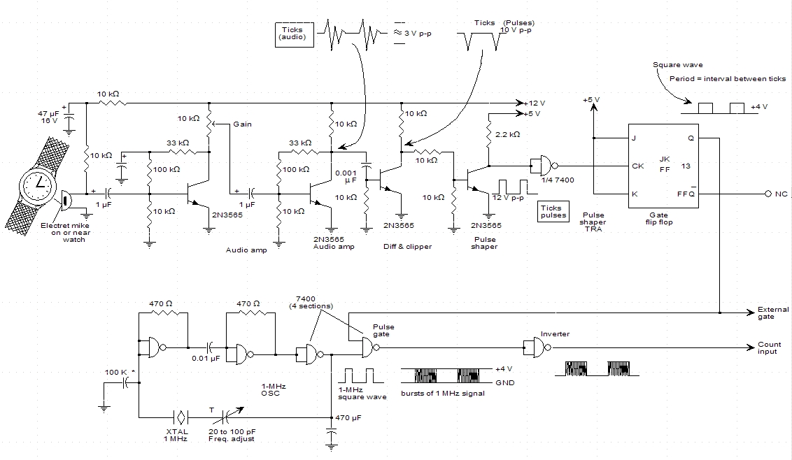
A schematic for a watch timer was found in a hobby electronics book. The circuit adapts a frequency counter to measure intervals. Watch ticks are clipped, shaped, and formed into a square wave. This square wave is utilized to...
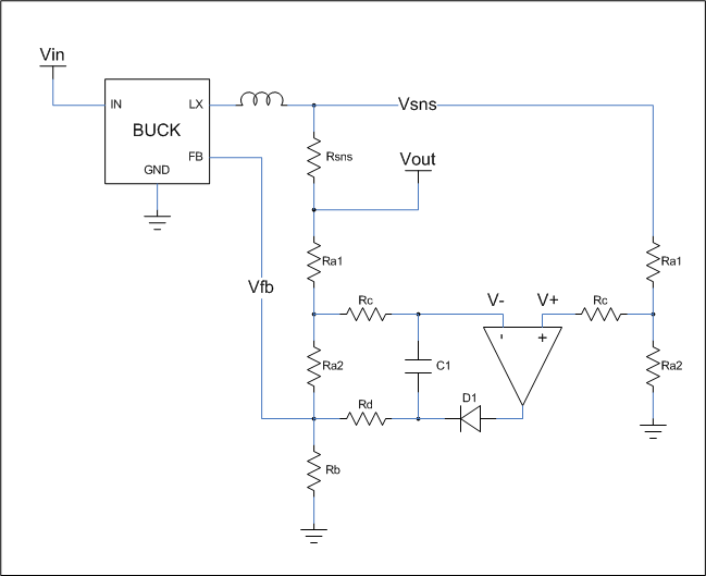
This is a cost-effective circuit that incorporates precise current limiting functionality into a voltage regulator. The circuit described is designed to enhance the performance of a voltage regulator by integrating a current limiting feature. This is particularly beneficial in applications...
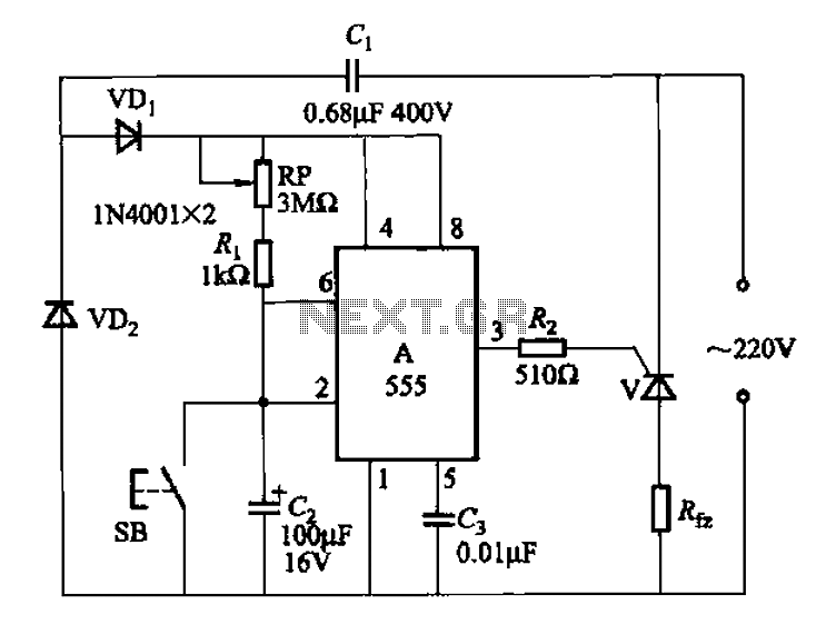
The 555 integrated circuit (IC) is utilized in a delay circuit configuration. It transitions from a high to a low output state when a button (SB) is pressed. The output remains high for a specified delay period before transitioning...
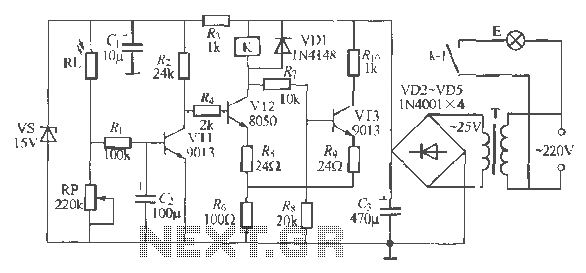
The circuit operates as a light-activated switch that controls white moving lights. It features high sensitivity, stable performance, and good anti-interference characteristics. A photosensitive resistor (RI) is employed to detect ambient light levels. During the day, the resistor exhibits...
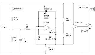
When the switch is pressed, capacitor C3 charges through resistor R4 with a time constant of 0.47 seconds. Upon releasing the switch, C3 discharges more slowly through resistors R7 and R3, with a time constant of approximately 5 seconds....
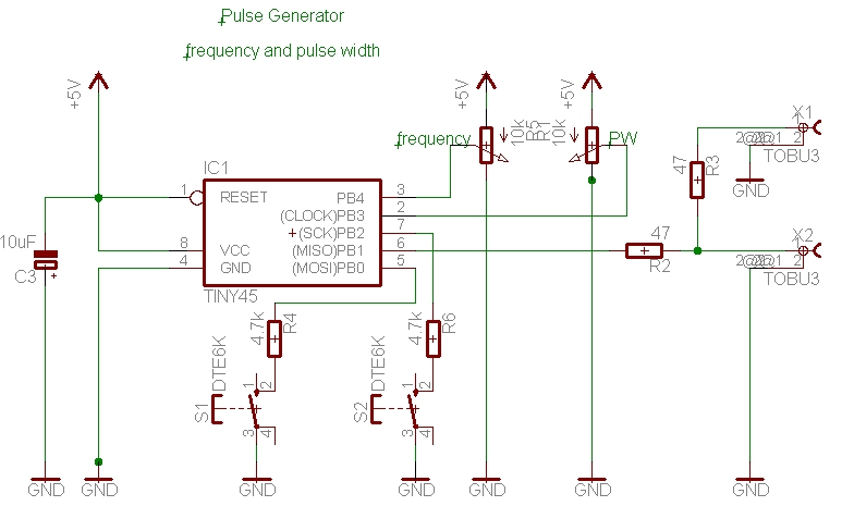
A simple pulse generator with a variable duty cycle and frequency is often useful in the lab to trigger or test other devices, such as a servo with a frequency of 50 Hz and pulses between 1 and 2...