
555 IC using a delay circuit of the four b
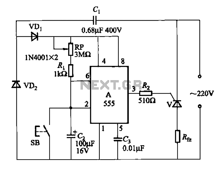
The circuit utilizes the 555 IC in monostable mode, where it generates a single output pulse in response to a triggering event. When the button SB is pressed, it triggers the 555 IC, causing the output to go high. The duration for which the output remains high is determined by the resistor (R) and capacitor (C) values connected to the 555 timer. The delay time (t) can be calculated using the formula t = 1.1 * R * C, where R is the resistance in ohms and C is the capacitance in farads. The inclusion of the adjustable potentiometer (RP) allows for fine-tuning of the resistance, thereby varying the delay time according to the application needs.
Once the delay time elapses, the output of the 555 IC transitions to a low state, effectively turning off the connected load. The load is powered through a unidirectional thyristor circuit, which is designed to conduct current only during one half of the AC cycle. This configuration ensures that the load receives power in a controlled manner, providing efficient operation and reducing the risk of overheating or damage to the components involved.
Overall, this circuit is suitable for applications requiring timed control of a load, such as in lighting systems, motor controls, or other automated processes where a delay is necessary before deactivating the load. The combination of the 555 timer, adjustable delay, and thyristor control creates a versatile and effective solution for various electronic applications.555 IC using a delay circuit of the four b They are a jump from high to low transition of the delay circuit. That button is pressed SB snow, the output is high, after some dela y, the output of the transition to the low level and remain low. Adjustment potentiometer RP, can change the delay time. Unidirectional thyristor circuit, called on to supply the load only half-wave power.
Related Circuits
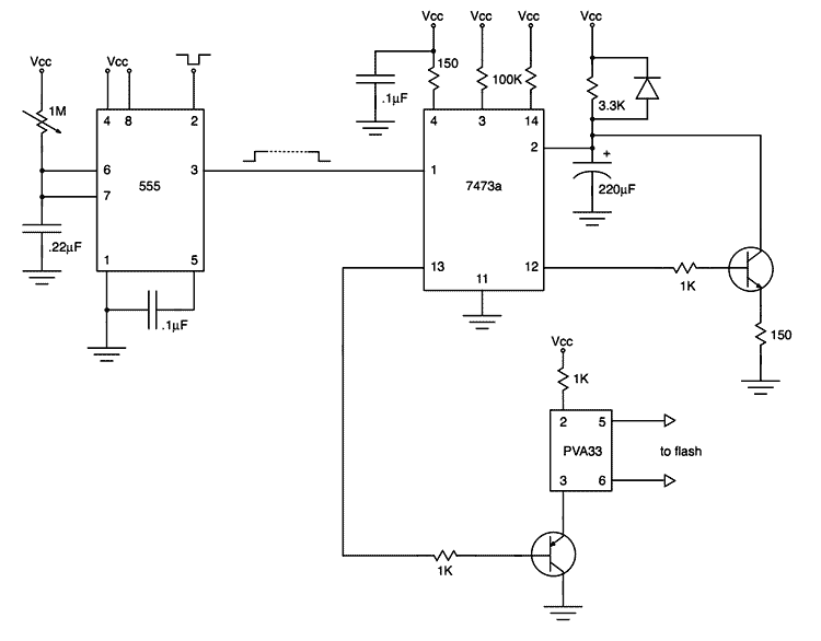
My first project after assembling an electronic design lab was to build a flash trigger that I could use for high-speed photography. I thought it would be useful to share not only the finished product but also the reasoning...
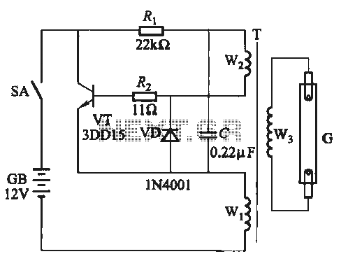
A self-excited transistor inverter circuit is designed for improved performance and features a relatively simple schematic. It is suitable for driving fluorescent lamps with a power rating between 8 to 40 watts. This inverter can operate stably even when...
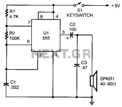
A 555 timer configured as an astable multivibrator is used in this circuit to generate an audio note. The capacitance value can be changed to vary the audio note as desired. The circuit utilizes a 555 timer IC, which...
Figure A, B, and C illustrate the test rod end clip, with a positive power supply terminating test equipment. The B and C ends are connected in series with the load, where C represents the negative side of the...

This is a UHF band TV antenna preamplifier circuit with a gain of 15 dB, built using a BF180 UHF transistor. The circuit is straightforward in design. The operational principle consists of two stages. The first stage features a...
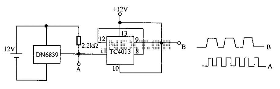
The circuit utilizes the integrated Hall element DN6839 for frequency division. It detects a magnetic field through the pulsating DN6839, generating a pulse waveform. The circuit is designed for applications involving very high-frequency pulsating magnetic fields. It employs the...