
Circuit Project: Wireless Doorbell
The wireless doorbell circuit exemplifies innovative design principles, particularly in its RF transmission capabilities. The use of a self-oscillating circuit highlights the efficiency of integrating passive components like capacitors and inductors to create a resonant tank circuit. The choice of operating frequency at 303 MHz is strategic, as it balances range and component size, allowing for compact design without sacrificing performance.
The addition of an antenna is a significant enhancement, demonstrating how simple modifications can yield substantial improvements in range and signal clarity. The careful selection of components, particularly the high-gain transistor, not only ensures reliable transmission but also allows for a robust design that can withstand variations in environmental conditions.
Moreover, the choke's role in managing current fluctuations is crucial for maintaining oscillator stability. By mitigating the effects of back-emf, the circuit can sustain its operational frequency, ensuring consistent performance. The design's resilience against stray capacitance further underscores its sophistication, making it suitable for practical applications.
Overall, this wireless doorbell circuit serves as an educational platform, illustrating fundamental electronic principles while offering insights into practical circuit design and optimization. The ability to learn from existing products fosters a deeper understanding of electronics, encouraging experimentation and innovation in future projects.It is a wireless doorbell with a cost of about $10. 00. So, we have to change our attitude to building projects and use items such as this to learn how things work and modify them to suit our own requirements. This doorbell uses quality components. It`s not rubbish. The circuit is quite unbelievable. You can not obtain some of the components individually and the effectiveness is magic. We have so much to learn! The first thing you will notice is the clever circuitry. Some of the design goes against everything we have learnt in electronics. That`s why we have to study other people`s designs and realise the more you know, the more you realise you don`t know. The oscillator circuit is very interesting, but first we will look at the RF oscillator. The doorbell operates on the 303MHz band and the 30 metre range (100ft) is obtained without the use of an antenna!
The circuit is actually radiating from the printed track of the tank circuit. The Tank Circuit is a single-turn coil and a small capacitor (5p & 4p in parallel). In this project we show how to add a small antenna to the circuit to get double the range plus two other improvements to increase the range. Some of the improvements will load the circuit and alter the frequency at which it operates. Others can be done without any effect on the circuit. Fortunately, the transmitting stage is what we call tight and is not affected by surrounding stray capacitance.
The circuit has been kept near the power rails by the use of a choke in the positive rail. The positive rail is then reflected to the negative rail via the battery. This feature helps us when we want to add an antenna. A 7cm length of tinned copper wire is connected to the collector of the transistor and bent around the board so that everything can be put back into the case. When the project was tested inside the authors house, the range was increased to double. When the transmitter was taken outside, the range was over 60 metres (200ft) and the full range could not be tested as the sound from the doorbell was too faint to be heard!
We can learn so much from a product that is already on the market. Firstly, you know it works, it is reliable and you know what can be built for $10. 00. Secondly, you know what type of components can be purchased cheaply and what to expect from them. In this case the transmitting transistor has the highest gain so they have taken a special effort to get a good quality transistor. Now, let`s look at the transmitter circuit: The transmitter circuit is made up of two building blocks the 303MHz RF oscillator and the 32kHz crystal controlled oscillator.
The 303MHz oscillator consists of a self-oscillating circuit made up of the coil on the PC board and a 9p (9 puff) capacitor (actually 4p and 5p in parallel). The circuit starts-up by the transistor producing noise. This rising-and-falling signal on the collector is passed to the parallel tuned circuit (the tank circuit) and the base sees a very smooth sinewave at a frequency of 303MHz.
This sinewave is then amplified by the transistor and this is how the 303MHz frequency is generated. Now we come to the purpose of the 15microhenry choke on the tank circuit. When the circuit oscillates, it takes a larger and small amount of current. . This current passes through the choke and the turns produce a back-emf or back voltage that fights against the flow (change) in current. The end effect is a voltage created at the point where the choke is connected to the track-work on the board.
This effectively allows the track work to produce a waveform and since the frequency of this wave is very high, a percentage of the energy is radiated into the air as electromagnetic energy. The choke allows the 🔗 External reference
Related Circuits

This is an intercom circuit that utilizes the LM380 as the audio amplifier and two transistors for the microphone preamplifier. The sound quality is sufficiently good while maintaining a low construction cost. The circuit comprises two identical intercom units,...
A unit that is often very useful for isolating two stages in sound circuits. This circuit incorporates an amplification unit with a gain of X1. It employs only local negative feedback rather than total negative feedback, resulting in very...
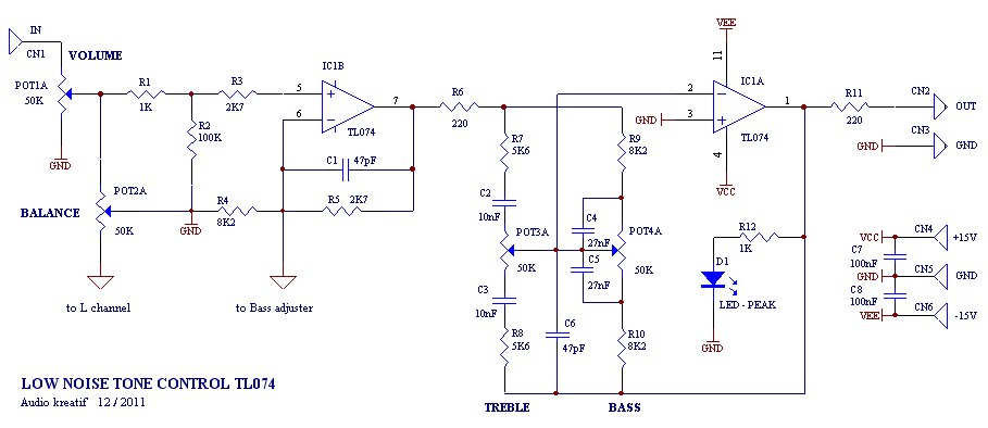
A tone control or pre-amplifier is an amplifier circuit that enhances audio signals. It is important to understand the characteristics, advantages, and disadvantages of various amplifier equipment, as the performance of different amplifiers may not show significant differences. The...
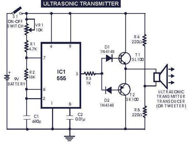
The circuit generates and transmits ultrasonic sound at frequencies between 40 and 50 kHz. It consists of a mini transmitter and a receiver circuit, where the transmitter produces ultrasonic sound, and the receiver detects this sound to activate a...

The circuit consists of two main sections: a charger power supply and an LED driver. The charger power supply is designed using a 3-terminal adjustable regulator (IC1) LM317, while the LED driver is based on a BD140 transistor (T2)....
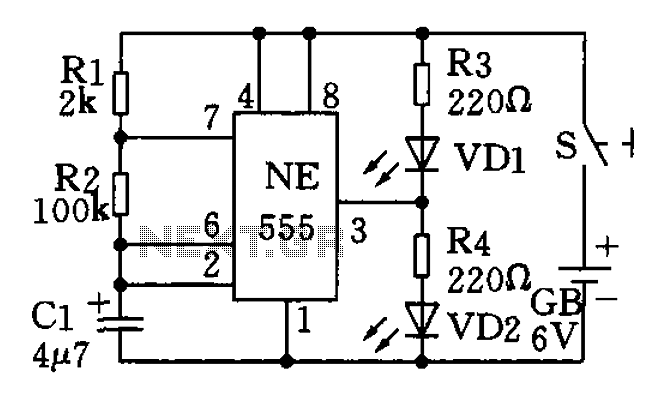
The circuit utilizes a 555 timer as the central component of a flashing light circuit. In normal operation, the light-emitting diodes (LEDs) VD1 and VD2 alternate flashing. The circuit comprises the NE555 timer, resistors R1 and R2, and capacitor...
Warning: include(partials/cookie-banner.php): Failed to open stream: Permission denied in /var/www/html/nextgr/view-circuit.php on line 713
Warning: include(): Failed opening 'partials/cookie-banner.php' for inclusion (include_path='.:/usr/share/php') in /var/www/html/nextgr/view-circuit.php on line 713