
Modular Class A Buffer preamplifier circuit

This circuit is designed to function as a two-stage amplifier, providing isolation between stages to prevent signal interference and maintain audio fidelity. The amplification unit operates with a gain of X1, ensuring that the input signal is preserved without excessive amplification, which could introduce distortion. The use of local negative feedback is critical in this design, as it minimizes distortion while maintaining a stable gain.
The selection of transistors is crucial for optimal performance. Transistors must be matched not only in terms of their electrical characteristics but also in terms of their thermal stability. Variations in transistor parameters can lead to imbalances that affect the circuit's overall performance. Additionally, the resistor placed between the transistors must be chosen carefully to ensure that the biasing conditions are met, allowing for linear operation of the transistors and minimizing the risk of distortion.
In practical applications, this circuit can be utilized in various audio processing scenarios, such as in mixing consoles, effects units, or any situation where signal integrity is paramount. The careful design and component selection contribute to a robust audio path that can handle a variety of input signals while maintaining clarity and reducing unwanted artifacts.A unit which is often very useful, if we need to isolate, in sound circuits, two stage between them. Then we can use this circuit which has an amplified unit, which gain X1, we do not use total negative feedback, only local, with the result that distortion remains at a very low level. Matching must be done with great care to the types of transistors, resistor between them.. 🔗 External reference
Related Circuits
The receiver circuit in Figure 1 activates an audio alarm when the transmitter (Figure 2) moves beyond a specified perimeter. The transmitter functions as a voltage-controlled oscillator, operating at approximately 915 MHz within the unlicensed ISM (industrial/scientific/medical) band. It...
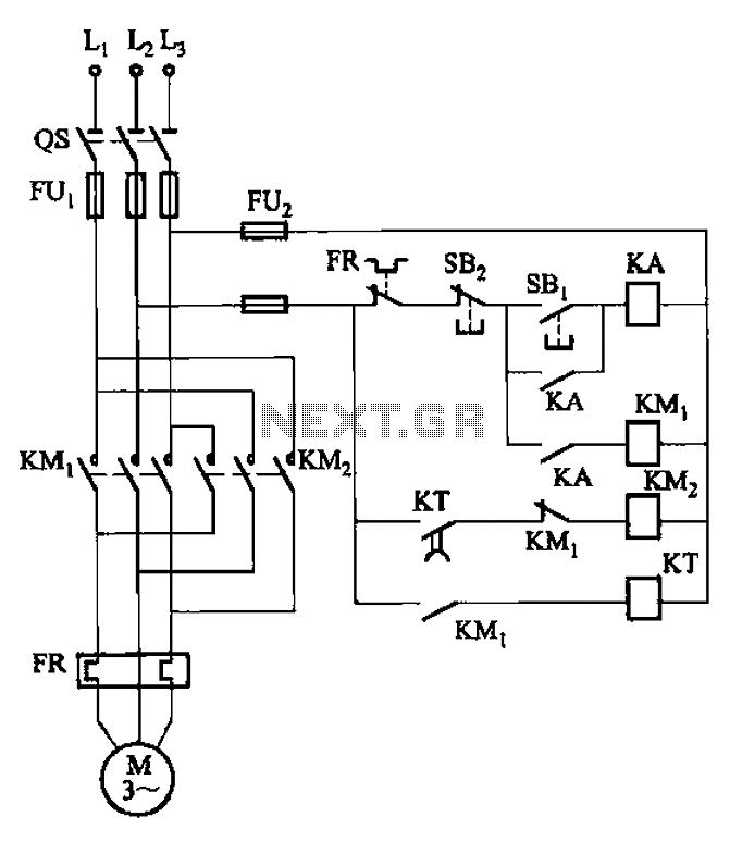
The circuit illustrated in Figure 3-127 utilizes a time relay (KT) in place of a speed relay. The timing duration is adjustable and typically set between 1 to 2 seconds. This circuit is designed to operate effectively in dusty...
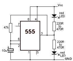
This LED flasher circuit utilizes the 555 timer integrated circuit (IC). The circuit diagram is straightforward and requires only a few external components. When operational, the red LEDs will flash sequentially at a predetermined frequency, similar to the indicators...
This circuit is designed to dim lights with a maximum capacity of approximately 350 watts. It employs a standard TRIAC circuit configuration, which has been observed to generate minimal heat during operation. It is important to note that this...
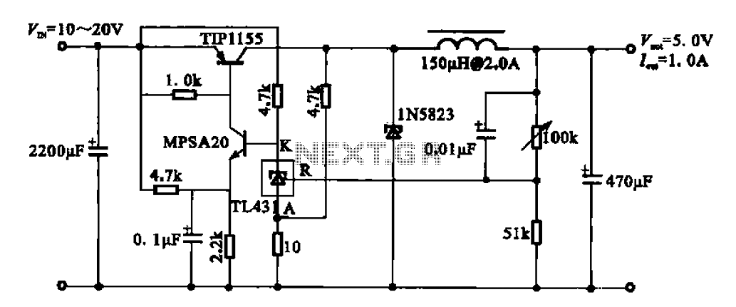
The 5V regulator circuit is designed to convert a DC input voltage ranging from 10V to 20V into a stable 5V output. This circuit features low power consumption and high efficiency. The 5V regulator circuit typically employs a linear voltage...
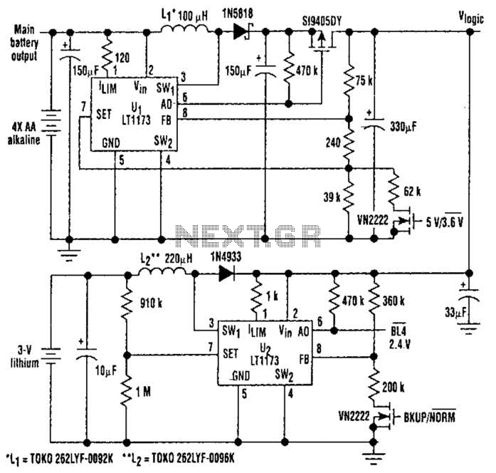
This unique logic-power-converter design allows for a switchable output of 3.6 V or 5 V at 200 mA using four AA cells. The supply features a MOSFET switch that can connect to a lithium backup battery, providing a 3.4...