
circuits and programs to show how to use PC parallel port output

The PC parallel port, also known as the Centronics port, is a versatile interface that allows for bidirectional communication between the computer and external devices. Traditionally used for connecting printers, the parallel port can also facilitate various hardware interfacing experiments, making it an excellent choice for hobbyists and engineers alike.
The parallel port typically consists of a 25-pin D-sub connector, with specific pins designated for data transmission, control signals, and ground connections. The data lines (D0-D7) are used for sending 8 bits of data simultaneously, allowing for efficient data transfer. Control lines such as Strobe, Ack, and Busy are essential for managing the flow of data and ensuring that the connected device is ready to receive information.
To utilize the parallel port for custom circuits, one of the first steps involves understanding the pin configuration. For instance, pins 2 to 9 correspond to the data bits, while pin 1 is the Strobe signal, which indicates that data is ready to be read by the connected device. Properly connecting these pins to a microcontroller or other digital logic circuits can enable various applications, such as controlling LEDs, motors, or sensors.
It is also important to consider the voltage levels when interfacing with the parallel port. The standard logic levels are TTL compatible, meaning that a high signal is typically around 5V, while a low signal is close to 0V. This compatibility allows for easy integration with common microcontrollers like the Arduino or PIC series.
For effective experimentation, it is advisable to implement a simple circuit that can toggle the data pins based on user input or predefined conditions. By employing basic programming techniques, users can create a series of commands that send specific signals through the parallel port, enabling real-time interaction with the connected hardware.
In summary, the PC parallel port serves as a practical I/O channel for a variety of interfacing applications. Understanding its pin configuration and voltage levels is crucial for successful integration with custom circuits, allowing for innovative and engaging hardware projects.PC parallel port can be very useful I/O channel for connecting your own circuits to PC. The PC`s parallel port can be used to perform some very amusing hardware interfacing experiments. The port is very easy to use when you first understand some basic tricks. This document tries to show those tricks in easy to understand way. 🔗 External reference
Related Circuits
You may be familiar with this effect. You switch audio equipment such as an amplifier to a different input and there is a loud click or "thump" in the speaker system. Not all equipment is affected. Some high-end audio...
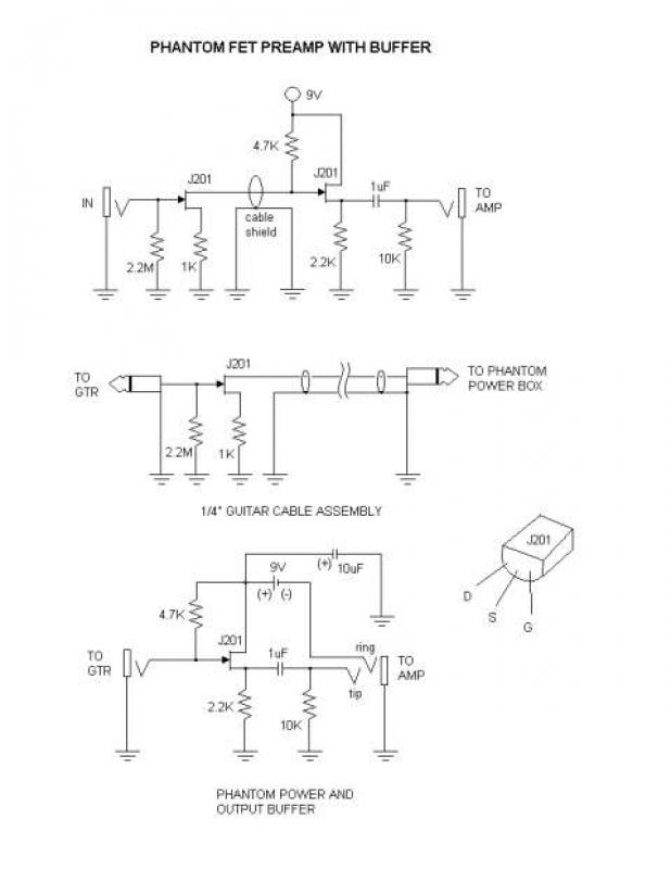
This is a phantom-powered FET preamplifier integrated into a 1/4" guitar cable, similar to the design found on the Tillman site. The amplifier consists of only a few components, making it challenging to trim and solder the leads to...
For a robot to perform its assigned tasks, a controller is necessary. This controller may be mechanical, electrical, electronic, or a combination of these. It acts as the brain of the entire system, providing the robot with its intelligence....
This text aims to clarify how to extract power from a PC serial port. Many small circuits derive their operating power from the serial port, despite the absence of dedicated power output pins. Examples of such circuits include PC...
The circuit employs two Light Dependent Resistors (LDRs) arranged in series with a separation of approximately half a meter. This configuration allows each LDR to detect the presence of a person entering or exiting the room. The processed outputs...
This is a minimal circuit designed for individual audio amplifier projects to control the presenter output relay. The purpose of this circuit is to manage the relay that activates the speaker output within the audio amplifier. The circuit introduces...