
Removing the "DC Thump" from Audio Circuits

In audio systems, switching between different inputs can lead to transient disturbances, often characterized by a loud click or thump in the speaker output. This phenomenon is primarily due to the presence of standing DC voltages at the outputs of various audio devices. In systems that utilize capacitors for DC blocking, the capacitors are designed to allow alternating current (AC) signals to pass while preventing direct current (DC) from reaching the output.
In typical audio circuits, the input stage may consist of a transistor that receives signals from multiple sources. When switching from one input to another, a charge imbalance occurs as the capacitors associated with the inputs or outputs attempt to equalize. This rapid change in voltage can produce an audible thump, which is particularly noticeable in systems that do not have adequate transient suppression mechanisms.
High-end audio systems often mitigate this issue through careful design, incorporating transformer coupling or other methods that effectively isolate the inputs from DC offsets. These methods ensure that the DC voltage does not interfere with the audio signal, thereby eliminating the thump when switching inputs.
In a typical audio switching circuit, the first input might show a standing DC voltage at the emitter of a transistor used in the amplification stage. This DC offset can lead to a momentary disturbance in the output signal when an input switch is engaged. To address this, it is common to include a series capacitor at the input stage of the amplifier to block any DC component.
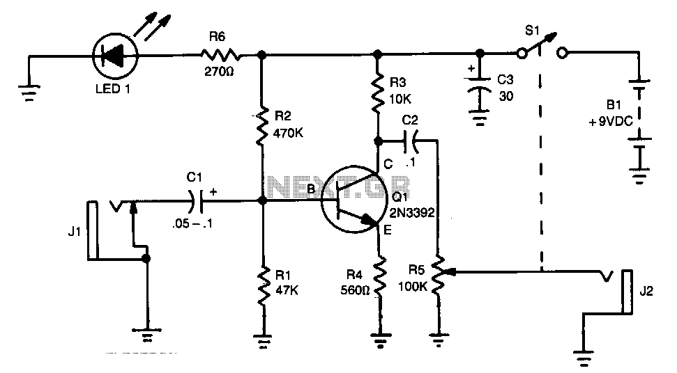
Implementing a well-designed audio switching circuit can significantly enhance the listening experience by reducing unwanted transients during input changes, ensuring that the audio output remains clean and free from audible artifacts. This is particularly important in professional audio applications where sound quality is paramount.You may be familiar with this effect. You switch audio equipment such as an amplifier to a different input and there is a loud click or "thump" in the speaker system. Not all equipment is affected. Some high end audio systems never suffer, but intercoms switching systems are often affected. Most audio outputs have some standing DC voltage which is separated by a capacitor. The capacitor will block this DC voltage while allowing the AC or audio to pass. Audio components using transformer coupling are not affected. The input to an amplifier may have a capacitive input or just a volume control. When switching inputs, charge is transferred through the switch as the input or output capacitors or both reach a state of equilibrium.
This takes only a fraction of a second and what you hear is the annoying dc thump. A typical circuit for audio switching is shown below. This is just an example. At input 1, there is a standing dc voltage on the emitter of the transistor in system A. Thi 🔗 External reference
Related Circuits
The final amplifier serves as the power source for every audio installation. Its function is to transform a small alternating voltage into a robust signal suitable for driving loudspeakers. The final amplifier, often referred to as a power amplifier, plays...
The amplifier's gain is nominally 20 dB. Its frequency response is primarily influenced by the values of a few components, mainly C1 and R1. The values in the schematic diagram yield a response of ±3.0 dB from approximately 120...
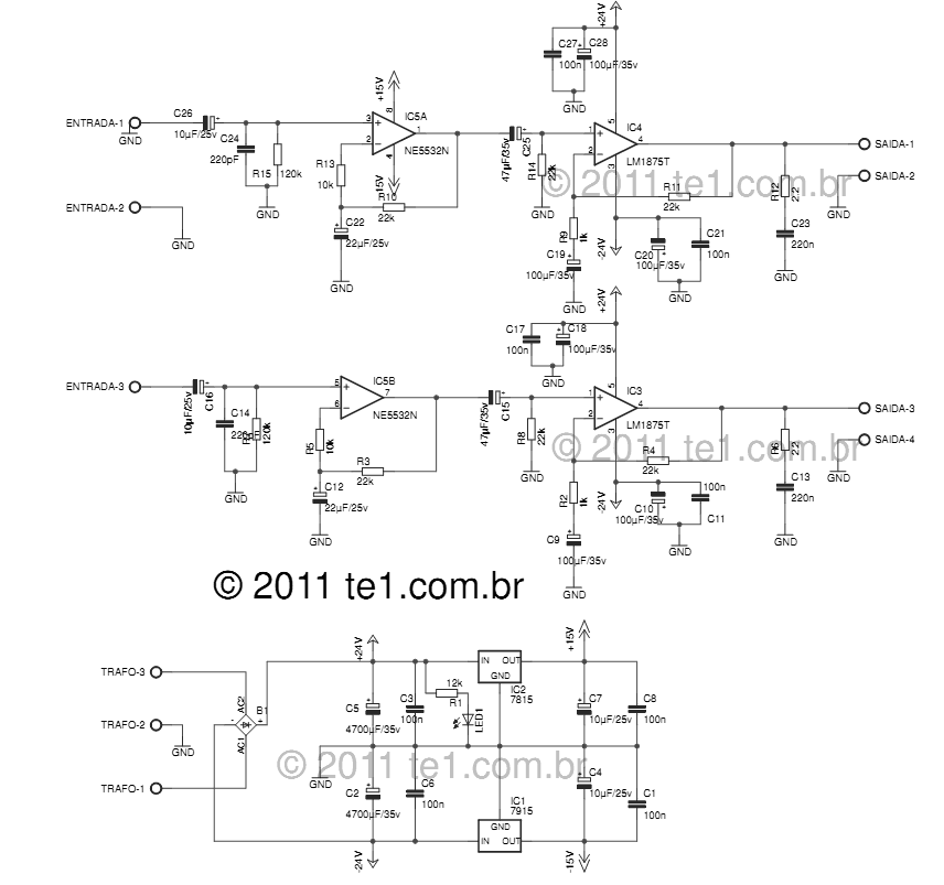
The LM1875 delivers 20 watts into a 4 or 8-ohm load on ±25V supplies. Using an 8-ohm load and ±30V supplies, over 30 watts of power may be delivered. The amplifier is designed to operate with a minimum of...
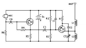
4 Stage FM Transmitter. This FM transmitter circuit utilizes four radio frequency stages, functioning as a VHF oscillator. It is available for wholesale through fmuser, including the CZE and CZH models of FM transmitters, which are suitable for OEM...
Burr-Brown DRV134 audio balanced line receiver schematic PCB/kit available? There is an interest in creating a balanced line receiver using the DRV134. The Burr-Brown DRV134 is an integrated circuit designed for audio applications, specifically for converting unbalanced audio signals...
The circuit operation begins by transmitting stereo surround sound signal quality information through the master volume circuit. This drives the left channel connected to the LCH Model TL072 IC1A and IC1B, which are linked to the right channel (Rch)....