
89c51 ds1820 based digital thermometer

The configuration of multiple DS1820 sensors on a microcontroller's 1-Wire bus offers a versatile solution for temperature monitoring applications. The simplicity of the 1-Wire protocol facilitates easy integration, requiring minimal wiring and setup. Each DS1820 sensor can be connected in parallel on the same data line, and the microcontroller, acting as the master, can communicate with each sensor individually through its unique ROM code. This unique addressing capability eliminates the need for additional lines for each sensor, significantly reducing complexity in circuit design.
The DS1820 sensor is designed to operate in a wide temperature range, making it suitable for various applications, including environmental monitoring, HVAC systems, and industrial temperature control. The sensor's accuracy of 0.5 °C ensures reliable readings for most practical applications.
In terms of programming, the One_Wire library simplifies interaction with the DS1820 sensors. The library includes functions for initiating temperature conversions, reading temperature values, and managing sensor addresses. This abstraction allows developers to focus on application logic rather than low-level communication details. Furthermore, the library's routines ensure compatibility with the Dallas OneWire protocol, enabling reliable data transmission.
When designing a circuit with the DS1820 sensors, it is essential to include a pull-up resistor on the data line to ensure proper signal levels. The recommended value for the pull-up resistor typically ranges from 4.7 kΩ to 10 kΩ, depending on the number of devices on the bus and the length of the wiring. Additionally, the circuit should be designed to accommodate the power requirements of the sensors, which can be powered directly from the 1-Wire bus or through an external power supply if necessary.
Overall, the integration of multiple DS1820 sensors via a 1-Wire bus provides a scalable and efficient solution for temperature measurement, with a focus on ease of use, reliability, and minimal hardware requirements.The hardware configuration when using multiple 1-Wire temperature sensors like the DS1820 is very simple, as illustrated in the block diagram below. A single-wire bus is used for communication between the microcontroller and the temperature sensor. It is also possible to power the devices direclty via this 1-Wire bus. An almost unlimited number of 1-WireTM devices can be connected to the bus because each device has a unique 64-bit ROM code identifier which is used to address each sensor Temperature measurement is one of the most common tasks performed by the microcontroller. A DS1820 sensor is used for measurement here. It is capable of measuring temperature in the range of -55 °C to 125 °C with 0. 5 °C accuracy. For the purpose of transferring data to the microcontroller, a special type of serial communication called 1-wire is used.
Due to a simple and wide use of these sensors, commands used to run and control them are in the form of functions stored in the One_Wire library. There are three functions in total: Concretely, you don`t have to study documentation provided by the manufacturer in order to use this sensor.
It is sufficient to copy some of these functions in the program. The OneWire library provides routines for communication via the Dallas OneWire protocol, e. g. with DS18x20 digital thermometer. OneWire is a Master/Slave protocol, and all communication cabling required is a single wire. OneWire enabled devices should have open collector drivers (with single pull-up resistor) on the shared data line. Each OneWire device has also a unique 64-bit registration number (8-bit device type, 48-bit serial number and 8-bit CRC), so multiple slaves can co-exist on the same bus.
🔗 External reference
Related Circuits
The capacitor charges until the PNP transistor (here shown as a 2N3906, but you could also use a BC327) receives base current through the Zener and turns on. Then the NPN transistor (here shown as a 2N3904, but you...
A highly accurate digital thermometer utilizing an LM35 probe with a resolution of 0.1 degrees Celsius. The circuit includes two adjustable components. The first, R5, is used to calibrate the display to zero. To perform this calibration, the end...
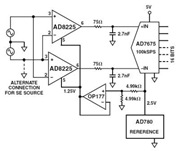
The Common Mode Rejection Ratio (CMRR) facilitates the rejection of high-frequency common-mode voltages, leading to the attenuation of elevated ambient noise levels from utility lines, industrial machinery, and other sources of radiation. The circuit diagram presented illustrates the advantages...
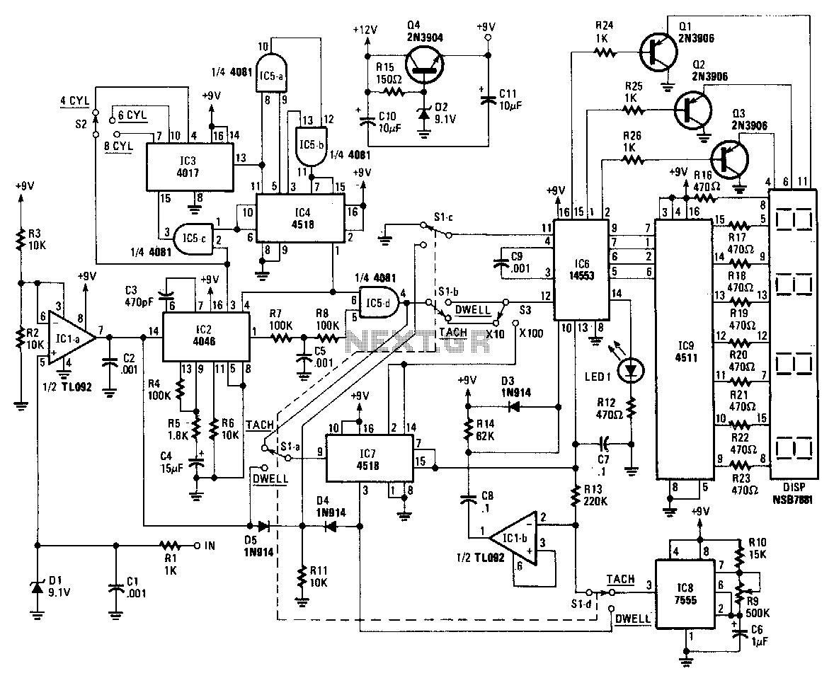
The core component of the circuit is ICZ, a 4046 micropower phase-locked loop (PLL). The incoming signals are processed through a buffer, IC1a, and its associated components before being fed into the PLL. The frequency of the incoming signal...
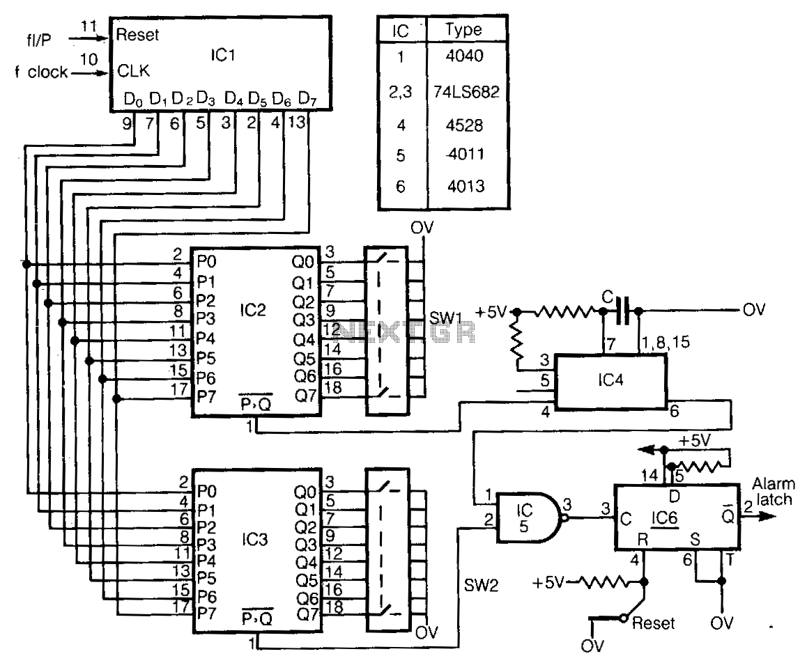
This circuit detects frequency variations that exceed preset limits. IC1 functions as a binary counter connected to the clock frequency (FcLK). The outputs from IC1 are compared with preset values set by IC2 and IC3. The input signal, which...
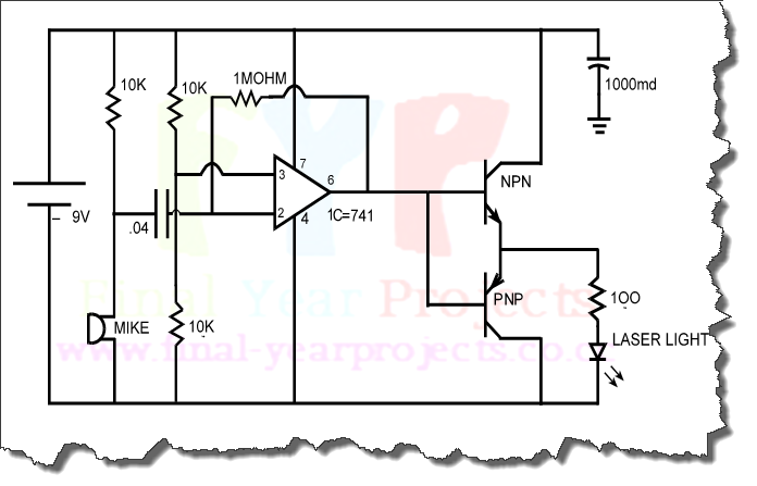
The objective of this project is to design a circuit for an electronic infrared communication system, develop innovative ideas for implementing this circuit, and study the circuitry along with various components such as DTMF generators, DTMF decoders, operational amplifiers,...