
A practical MS Decoder Circuit
To facilitate phase adjustments, patch cords can be utilized if the console supports phase switches, though caution is advised as some consoles only provide phase switching on the channel microphone preamp rather than the channel itself. By patching out of the preamp on the first channel and into the line input of the next channel, it may be necessary to employ a half patch technique, which is not covered in this discussion. Prior to panning hard left and right, both channels should be centered, and the level on the second channel should be adjusted until the Side signal is completely canceled, indicating matched signal levels. Once this is achieved, one channel can be panned hard right while the other is panned hard left. Most multi-track audio programs, such as Studio Vision Pro and Pro Tools, offer similar functionalities. The Side signal can be sent pre-fader to an effects bus, with the original channel panned hard right. The effects bus can then phase invert the signal and pan it to the opposite channel of the original, completing the setup.
The primary advantage of utilizing a dedicated MS Decoder lies in the ability to monitor the effect in real-time while positioning microphones and making adjustments prior to recording. Past experiences have shown that recording Mid and Side signals directly may not yield compatible results during playback and mixdown, underscoring the importance of this real-time monitoring capability.The schematic diagram of the MS Decoder may look complicated but is actually quite simple. Both the Mid and Side signals are initially buffered by unity gain inverting buffers formed around IC1b and IC2 b. This is necessary for two reasons, first to ensure enough drive current for the following sections. Second, the final summing sections invert t he signal, to achieve zero phase shift through the unit, one more stage of phase inversion is required. The Mid signal goes to level control potentiometer R15. It is then fed equally to the left and right summing amplifiers, which are formed around the two sections of IC3.
The use of R15 (and R16) is to allow adjustment of the relative levels of the mid/side levels independent of the mic-pre gain setting. This is useful for directly feeding a recording device. The Side signal has a little different path. After initial buffering, it is fed to the right summing amplifier via one section of dual potentiometer R16.
It is also fed to a unity gain inverter formed by IC2a and its associated resistors. This inverted signal goes to the other half of the dual ganged potentiometer section. Then it is summed into the left channel via IC3a. One section of IC1 is not used. Both of its inputs are tied to ground to keep any thing strange from happening. OK, so what are R19 and R20 doing That is an interesting question. These are there to load down R16 so that when the levels of the Side signal are adjusted the potentiometer gives the same feel as the Mid level adjustment potentiometer R15. The op-amp summing sections are virtual grounds. This means that signals entering the op-amp see a load equal to the input resistor. All of these are 10K resistors. The Mid potentiometer feeds two of these so it is presented with a 5K load. To make the load on the Side potentiometer the same one additional 10K resistor tied to ground is added to each wiper so it sees 5K also.
Here is the other interesting thing that all of this causes. Because all the potentiometers are linear taper, loading them down with a load much smaller than the resistance of the potentiometer causes a change in the characteristics of the potentiometer. This in essence, makes them respond more logarithmically than linearly, which is the way we hear anyway which is a good thing!
Well, you can always break out the patch cords if your console supports phase switches. Be careful, some only have the phase switch on the channel microphone pre-amp, not the channel itself. Simply patch out of the preamp on the first channel and into the line input on the next channel. Depending on the patch bay, you may need to use a half patch technique, which is beyond the scope of this article.
Before panning hard left and right, center both and adjust the level on the second channel until the side signal is completely cancelled. This means that you have the signal levels matched. Now pan one hard right and the other hard left. Most multi-track audio programs allow you to do this too. I use Studio Vision Pro and Pro Tools but I know most others have similar features. Take the side signal pre fader and send it to an effects buss. On the original channel pan it hard right. On the effect buss, phase invert the signal and pan it to the opposite channel as the original. Voila! You are done. There are usually many ways to skin a cat. So why build or use an outboard MS Decoder The real benefit from having a dedicated MS Decoder is that you can listen to the effect in real time while you position the microphones and make adjustments before recording.
I have in the past, recorded the Mid and Side signals directly only to find out they really didn`t work together while decoding during playback and mix down. We were recording a Leslie and fortunately after taking my lumps, I was able to re-record it. I had to buy a round of beers over that one. Just patch the Project r MS decoder between your microphone pre-a 🔗 External reference
Related Circuits
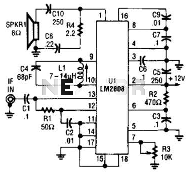
An LM2808 performs IF amplification of the 4.5-MHz sound subcarrier, limiting, detection, and audio amplification. If the center frequency must be changed, then change L1/C4. Audio output is 0.5 W. R3 is the volume control. The LM2808 is an integrated...
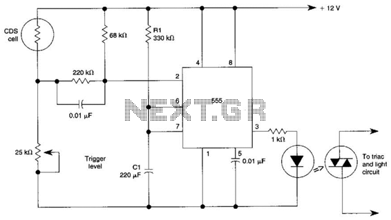
This circuit can control the on/off cycle of a light using a CDS photocell and turn it off after a preset period. The light can only be activated when the CDS cell is in darkness, and it remains on...
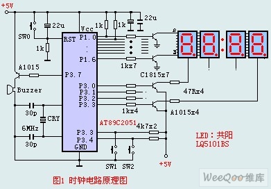
The circuit design incorporates an anodic Nixie tube for the LED display. It utilizes the LQ5101BS general luminous diode, with the driving transistor being either the 2SA1015 or 2SC1815 types, which are readily available. Additionally, low-power transistors such as...
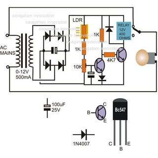
This circuit diagram illustrates a light-activated switch utilizing the National Semiconductor comparator IC LM311 and a light-dependent resistor (LDR). The configuration is based on a voltage comparator circuit centered around IC1. The non-inverting input of IC1 receives a reference...
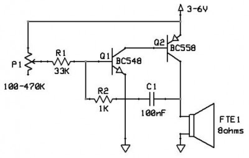
This circuit functions as an oscillator, capable of generating a sound wave or tone. The frequency of the tone, whether high or low, is adjustable via a variable resistor. The volume produced by this circuit is substantial; therefore, it...
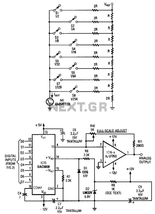
Figure A illustrates an R/2R resistor ladder. Each closed switch increases the current flow. A basic channel A/D converter is depicted in Figure B. The voltage reference (D2) is shared across all channels, although the value of the dropping...