
Porch Light Control Circuit

The described circuit utilizes a light-dependent resistor (CDS photocell) to detect ambient light levels. When the light intensity falls below a certain threshold, indicating darkness, the photocell allows current to flow, triggering the operation of the circuit. The heart of the timing function is the 555 timer IC, configured in monostable mode. In this configuration, the 555 timer generates a single output pulse when triggered, with the pulse duration defined by the resistor (R1) and capacitor (C1) values.
The relationship between R1, C1, and the output time (T) can be expressed by the formula T = 1.1 * R1 * C1. For instance, if R1 is set to a specific value in ohms and C1 is a capacitor measured in farads, the resulting time period can be calculated to achieve the desired on-time for the light. In this case, with the component values provided, the on-time is approximately 80 seconds.
To ensure proper functionality, the circuit should include a power supply compatible with the 555 timer IC and the light load. Additionally, a transistor or relay may be employed to switch the light on and off, depending on the current rating of the light source. The design must also incorporate protective elements such as diodes to prevent back EMF from inductive loads, ensuring the longevity and reliability of the circuit.
This circuit is ideal for applications such as outdoor lighting, where automatic control based on ambient light conditions can enhance energy efficiency and provide convenience. Proper layout and soldering techniques should be employed to minimize noise and ensure stable operation of the photocell and timer circuit. This circuit can control the on/off cycle of a light via a CDS photocell, and turn it off after a preset period. The light can only be turned on when CDS cell is in darkness, and it stays on for a time determined by the 555 circuit.
On time depends on R1 and CI and is about 80 seconds with the values shown.
Related Circuits
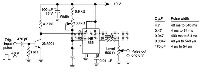
This pulse generator can enhance a standalone pulse generator. By utilizing a transistor and a 555 timer, it can produce pulse widths ranging from 5 microseconds to 500 microseconds. The value of capacitor C3 can be approximately determined using...
One of the more advanced PCB manufacturing methods involves exposing laminate copper boards that are covered by a photoresistive layer through a mask. Utilizing UV light in the production of PCBs offers several advantages over other techniques. This method...
Using two LT1228 transconductance amplifiers in front of a current feedback amplifier creates a video fader. The ratio of the set currents into pin 5 determines the ratio of the inputs at the output. The proposed circuit utilizes two LT1228...
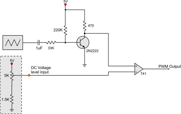
Circuits that generate PWM pulses typically translate a resistor value into a change in duty cycle. While this method is convenient, there are instances where a voltage-controlled PWM generator is required. Although microcontrollers can produce a variety of PWM...
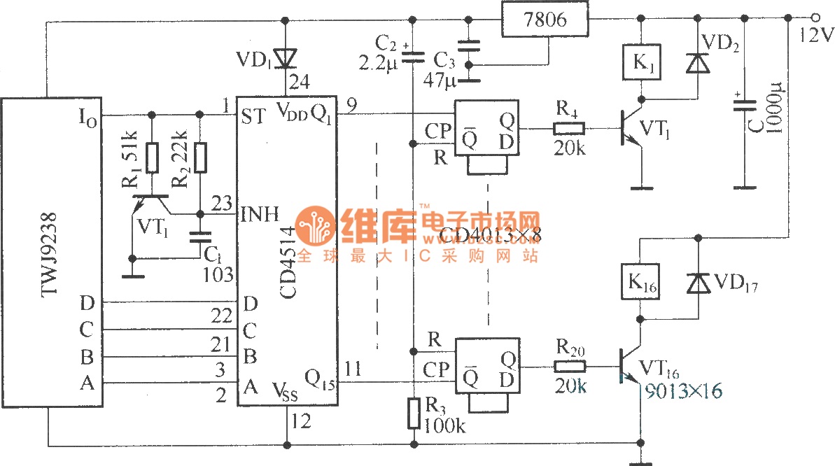
The Sixteenth Street control circuit consists of a secondary decoding output control circuit. Each output terminal of the sixteen decoding is connected to a bistable circuit made up of dual D flip-flops (CD4013). A DC relay is connected to...
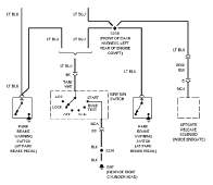
The following circuit illustrates the wiring diagram and electrical circuit troubleshooting for the 1997 Chevrolet Blazer. Features include a 4.3-liter Vortec V-6 engine, an AM-FM stereo radio with CD player, rear-wheel drive managed by a four-speed automatic transmission, air...