
AM Transmitter
This AM voice transmitter circuit operates within the frequency range of 500 kHz to 1600 kHz, making it suitable for voice transmission applications. The design features a microphone pre-amplifier that amplifies the audio signal from an electret condenser microphone, ensuring sufficient modulation levels for transmission. The RF oscillator, configured as a Hartley oscillator, allows for variable tuning by adjusting the tank circuit components, which include the inductor (L1) and capacitor (C1).
The circuit's output is designed to be fed into a long wire antenna, which serves as the transmission medium. The choice of a long wire antenna enhances the transmission range while ensuring compliance with the circuit's power limitations. The use of coaxial cable for the antenna connection minimizes signal loss and helps maintain a clear ground reference, which is critical for effective RF transmission.
To ensure stable operation, the circuit incorporates various passive components that filter out unwanted frequencies and harmonics, thus enhancing the overall performance of the transmitter. The careful selection of resistors and capacitors in the circuit is essential for achieving the desired gain and frequency response, while also preventing interference between the audio and RF sections of the circuit.
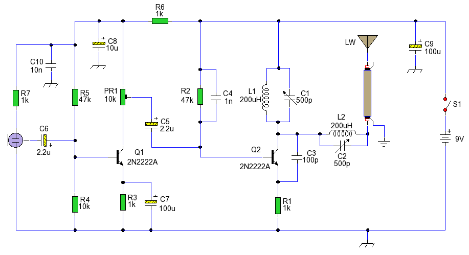
The schematic layout highlights the interconnections between components, illustrating how the feedback mechanism facilitates oscillation in the RF stage. Additionally, the design considers safety and legal aspects by limiting the power output, making it suitable for educational experimentation within the constraints of regulatory compliance.An AM voice transmitter with variable tuning. The antenna circuit is also tuned and transmits via a long wire antenna. Please Note. It is illegal to transmit on the AM wavebands in most countries, as such this circuit is shown for educational purposes only. Please read the disclaimer on this site before making any transmitter circuit. It is illega l to operatea radio transmitter without a license in most countries. This circuit is deliberately limited in power output but will provide amplitude modulation (AM) of voice over the range 500kHz to 1600kHz with values shown. You can input values in the calculator below, remember to change drop down box to picofarads for capacitance and microhenries for the coil.
The coil is fixed at 200uH, the capacitor values can be varied and resonant frequency found by using the calculator below. The circuit is in two parts, a microphone pre-amplifier built around Q1 and an RF oscillator circuit (Q2).
The oscillator is a standard Hartley oscillator which is tunable. Tank circuit L1 and C1 control frequency of oscillation, the power in the tank circuit limited via emitter resistor R1. The transmitter output is taken from the collector, L2 and C2 form another tuned tank circuit and help match the antenna.
L1, L2, C1 and C2 may be salvaged from an old AM radio if available. The antenna should be a length a wire about 10 feet or more. In the schematic I have shown coaxial cable to be wired to the "longwire" antenna, the outer coax shield returned to ground. Ground in this case is a cold water pipe, however even without a ground and coax cable a signal should still be possible.
L2 and C2 not only help match the antenna to the transmitter, but also help remove harmonics and spurious emissions in the transmitter circuit caused by non linearity in the transistors. Q2 needs regenerative feedback to oscillate and this is achieved by connecting the base and collector of Q2 to opposite ends of the tank circuit which is achieved by C4.
C3 ensures that the oscillation is passed from collector, to emitter, via the internal base emitter resistance of the transistor, back to the base again. Emitter resistor R1 has two important roles in this circuit. It ensures that the oscillation will not be shunted to ground via the very low internal emitter resistance, re of Q2, and secondly raises input impedance so that the modulation signal will not be shunted.
Q1 is wired as a common emitter amplifier, C7 decoupling the emitter resistor and realizing full gain of this stage. Bias of this stage is controlled by R4, R5 and R3. The microphone is an electret condenser type microphone, R7 setting operating current of the ECM and C6 providing DC blocking.
The amount of modulation is controlled by the 10k preset resistor PR1 which is also the collector load. The preamp stage is decoupled by R6, C8 and C10. This ensures no high freqency feedback from the oscillator gets into the audio stage. Some electrolytics capacitors have a high impedance at radio frequencies, hence the use of C10, a 10n ceramic to bypass any oscillator frequencies.
🔗 External reference
Related Circuits
FM Broadcast Audio Transmitter. The circuit includes a frequency-modulated oscillator, an audio preamplifier with pre-emphasis to provide the frequency-modulating signal, and a buffer amplifier to drive the antenna connector. The FM radio pirate introduction to community radio electronics presents...
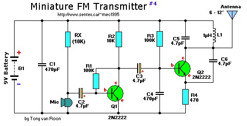
This is a mini FM transmitter designed by Tony van Roon, powered by two transistors. It is straightforward to assemble, and its transmissions can be received on any standard FM radio. The transmitter has an approximate range of 1/4...
This circuit enables the generation of audio musical notes that can be heard from a distance of up to 10 meters. It consists of two main components: an infrared (IR) music transmitter and an IR music receiver. The IR...

This project involves constructing a simple 3-stage low-power broadcast-type circuit, utilizing a crystal oscillator integrated circuit and a collector modulated AM oscillator with an amplifier. The circuit can be connected to an electret microphone or an amplified dynamic microphone,...
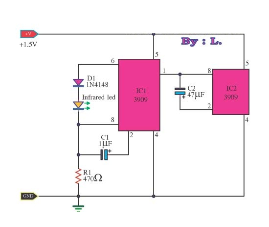
This circuit is an infrared transmitter that operates on a low power supply of 1.5 V. The main components include two LM3909 integrated circuits, which function as an oscillator and LED flasher. Typically, this circuit is utilized as a...

This circuit is designed to generate audio musical notes that can be heard from a distance of up to 10 meters. The circuit consists of two main components: an infrared (IR) music transmitter and an IR music receiver. The...