
IR Music Transmitter and Reciever

The IR music transmitter circuit is centered around the UM66 melody generator, which is capable of producing a variety of musical tones. The output of this IC provides a signal that is amplified and modulated by the subsequent driver stage formed by transistors T1 and T2, ensuring that the transmission is strong enough to reach the intended distance. The flickering of LED1 serves as a visual indicator of the modulation corresponding to the audio output, providing a useful debugging feature during the circuit's operation.
In the receiver section, the A741 operational amplifier plays a critical role in amplifying the weak signal received by phototransistor T3. This amplification is necessary due to the inherent losses that occur during infrared signal transmission. The gain adjustment via VR1 allows for fine-tuning based on the distance and environmental factors affecting the IR signal. Following the A741, the LM386 audio amplifier further boosts the signal to a level suitable for driving the loudspeaker, ensuring that the musical notes generated can be heard clearly.
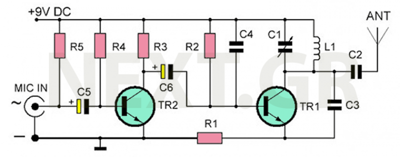
The use of variable resistors (potentiometers) VR1 and VR2 provides flexibility in adjusting both the gain of the amplifier and the volume of the output sound, respectively. This design allows for user-friendly operation and adaptability to various listening environments. The overall architecture of this circuit not only demonstrates the principles of infrared communication but also highlights the integration of audio generation and amplification in a compact form factor, making it a practical project for audio enthusiasts and electronics hobbyists.Using this circuit, audio musical notes can be generated and heard up to a distance of 10 metres. The circuit can be divided into two parts: IR music transmitter and receiver. The IR music transmitter works off a 9V battery, while the IR music receiver works off regulated 9V to 12V. First diagram shows the circuit of the IR music transmitter. It u ses popular melody generator IC UM66 (IC1) that can continuously generate musical tones. The output of IC1 is fed to the IR driver stage (built across the transistors T1 and T2) to get the maximum range. Here the red LED (LED1) flickers according to the musical tones generated by UM66 IC, indicating modulation.
IR LED2 and LED3 are infrared transmitting LEDs. For maximum sound transmission these should be oriented towards IR photo-transistor L14F1 (T3). The IR music receiver uses popular op-amp IC A741 and audio-frequency amplifier IC LM386 along with photo-transistor L14F1 and some discrete components (second diagram). The melody generated by IC UM66 is transmitted through IR LEDs, received by phototransistor ceived by phototransistor T3 and fed to pin 2 of IC A741 (IC2).
Its gain can be varied using potmeter VR1. The output of IC A741 is fed to IC LM386 (IC3) via capacitor C5 and potmeter VR2. The melody produced is heard through the receiver`s loudspeaker. Potmeter VR2 is used to control the volume of loudspeaker LS1 (8-ohm, 1W). Switching off the power supply stops melody generation. We aim to transmit more information by carrying articles. Please send us an E-mail to wanghuali@hqew. net within 15 days if we are involved in the problems of article content, copyright or other problems. We will delete it soon. 🔗 External reference
Related Circuits

In this circuit, a 74HC14 hex Schmitt trigger inverter functions as a square wave oscillator to drive a small signal transistor configured as a class C amplifier. The oscillator frequency can be set to a fixed value using a...
The recommended transmitter is straightforward to construct and suitable for beginners. Despite its simple design and compact size, it delivers remarkable performance. It operates for 12-15 hours on a 9-volt battery and has a transmission range of 100 to...
This will probably be one of the last transmitters for the 88MHz to 108MHz band. This particular TX is of special interest to those wishing to build low power Power Amplifiers for the VHF bands since it used impedance...

The AVR Basic Infrared Transmitter is a companion project to the Basic Infrared Receiver. This project is termed "basic" because it can be constructed using only 10 discrete components along with a standard AVR microcontroller. Together, these two projects...
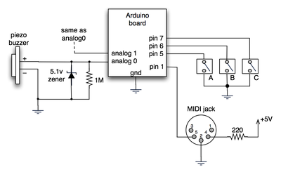
The notes for the fourth and final class are available on the Spooky Arduino class page. At the conclusion of the class, Mark from Machine Project awarded each student a merit badge. A project utilizing techniques from this week's...

This circuit diagram is part of an RF circuit. It features an FM transmitter circuit diagram using the BH1417 integrated circuit from RHOM, which incorporates multiple functionalities in a compact design. The IC includes pre-emphasis and a limiter to...