
Amplitude Modulation

One application of the AD633 is in an amplitude modulator circuit, where the carrier and modulation inputs are multiplied to generate a double sideband signal. The carrier signal is directed to the Z input of the AD633, where it is combined with the double sideband signal to produce an output that includes the carrier. Another application is in a voltage-controlled low-pass filter, where the cutoff frequency is modulated by a control input. By varying the control voltage, the frequency response of the filter can be analyzed and plotted. Such low-pass filters are commonly utilized in electronic music to create filter sweeps by gradually changing the cutoff frequency.
The equation used for the modulation process can be modeled to generate an AM waveform using a sine wave for the modulating signal and a square wave for the carrier signal. For implementation, the carrier is designed as a square wave with an amplitude of 6 V and a frequency of 10 kHz. The square wave is configured to oscillate between +6 V and -6 V by adding an offset of -6 V. The sine wave modulating signal is adjusted to include an offset of 6 V, with its amplitude determined by a modulation index, set here at 50%. The amplitude of the sine wave is then configured to 3 V with a frequency of 1 kHz. The two signals are multiplied using the AD633, thereby modeling an AM system based on the established equation.
This example illustrates just one of the numerous systems that can be modeled using the AD633 in various configurations. The methodology can be expanded to incorporate different signal types, such as sine, triangular, and square waves, serving as either carrier or modulating signals. The foundational concept revolves around deriving the equation for a system and implementing it through simulation tools, enabling straightforward modeling of fundamental operations like addition, subtraction, division, and multiplication.This is a functionally complete, four-quadrant, analog multiplier. Four quadrant means that both operands that are multiplied can take any polarity i. e. +/- and hence multiplication can happen across 4 quadrants. It includes high impedance, differential X and Y inputs, and a high impedance summing input (Z). Thus this multiplier basically does a MAC operation (Multiply and Accumulate). The AD633 is well suited for such applications as modulation and demodulation, automatic gain control, power measurement, voltage-controlled amplifiers, and frequency doublers. The input range of operating voltages for this IC is from +15 V to -15 V. So while designing circuits with AD633 keep in mind that the inputs do not exceed this limit. Typically this IC provides a bandwidth of 1 MHz. [1] Let`s check out a few applications using AD633 on DoCircuits. First up, given below is an amplitude modulator circuit. ( Click on the circuit to load it on DoCircuits) The carrier and modulation inputs to the AD633 are multiplied to produce a double sideband signal.
The carrier signal is fed forward to the Z input of the AD633 where it is summed with the double sideband signal to produce a double sideband with the carrier output. Here is how the AM signal generated looks like: Another very simple application using the AD633 is the voltage controlled low pass filter.
The cutoff frequency is modulated by EC, the control input. ( Click on the circuit to load it on DoCircuits ) Now to show how you can control this low-pass filter we can sweep the control voltage (Vdc) from 0. 01 V to 0. 02 V (this is done by selecting Frequency Domain Analysis and enabling the sweep settings. Then vary the Vdc values as given) and plot the frequency response as shown: So where can we find such a low-pass filter In some popular electronic music styles, filter sweeps have become a common effect.
These sweeps are created by varying the cutoff frequency of the VCF (sometimes very slowly) [2] This equation is used for a sine carrier and sine modulating wave. Let`s see how by modelling this equation and making a few changes we can model an AM waveform for a sine wave modulating signal and square carrier signal.
If I were to directly implement the above equation using ideal components it will look like this: ( Circuit Here ) The carrier is supposed to be a square wave of amplitude 6 V and frequency 10 kHz. From this frequency the square wave TL and TH are set as 0. 05 ms. Since for the square wave source U value is a peak-to-peak amplitude, we add an offset of -6 V to get the amplitude from +6 to -6.
From the equation it is known that an offset of A should be added to the modulating wave. A here is the amplitude of the carrier wave. Thus the sine wave modulating wave is given an offset of 6 V. The amplitude of the sine wave is determined by the modulation index. Say I want a modulation index of 50%. Thus the amplitude of the sine modulating wave is set as 3 V with a frequency of 1 kHz. These two signals are multiplied with the help of a multiplier. There you go, we have modelled an AM system from the equation for AM. Whether we are successful is yet to be seen. Simulating the above circuit gives the following output: This example is just one of many types of systems that can be modelled in DoCircuits. Of course you can extend the above method to all the different types of signals like sine, triangular, square etc.
both as carrier and modulating wave. But what is the idea behind it all It all started by getting the equation for a system and trying to implement it by modelling it in DoCircuits. Basic operations like addition, subtraction, division and multiplication are available in the ideal components panel and can be modelled very easy at present and further operations will be added in the future.
Last week we saw h 🔗 External reference
Related Circuits
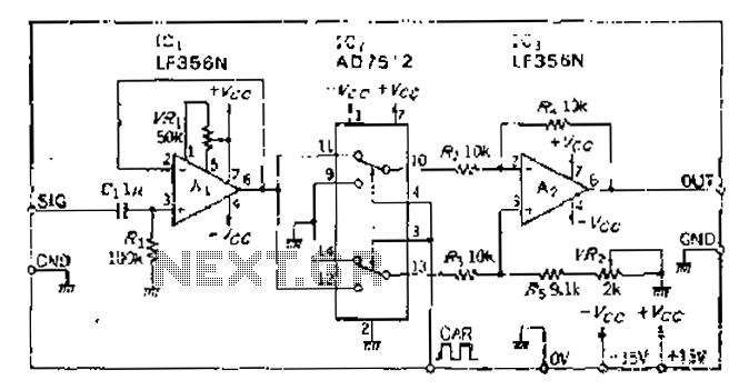
An analog switch (double loop, double-break) and a differential modulation amplifier are used in this circuit. The carrier control switch operates by switching contacts at specific times, inverting the input modulation wave. When the next carrier signal is applied...
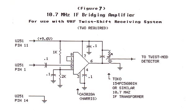
The material in this section demonstrates the construction of the Twist-Shift system for VHF utilizing commonly available surplus land mobile VHF transceivers that have been modified to operate on the 2-meter ham band. The radios employed in this project...
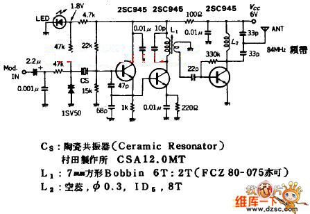
The quartz crystal oscillator circuit is highly advantageous in terms of frequency stability. Even the Voltage-Controlled Crystal Oscillator (VCXO) circuit, which allows for significant frequency changes, typically experiences only about a 1% variation. However, the linear range of control...
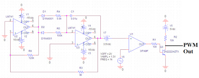
Pulse Width Modulation (PWM) is a highly efficient control scheme utilized to regulate the flow of power through various electronic devices. It is commonly found in switched-mode power supplies, LED dimming circuits, and variable speed motor controls, among other...

This simple pulse width modulation (PWM) DC motor control addresses common issues by regulating motor speed through the application of short pulses. The duration of these pulses is varied to adjust the motor speed; longer pulses result in faster...
The figure illustrates the FM modulation circuit of a crystal oscillator. FM modulation can be achieved through direct and indirect methods. The direct FM method involves directly altering the frequency of the oscillating circuit. While this approach is straightforward,...