
Antenna Tower Electrical Circuit Schematic Wiring Diagram
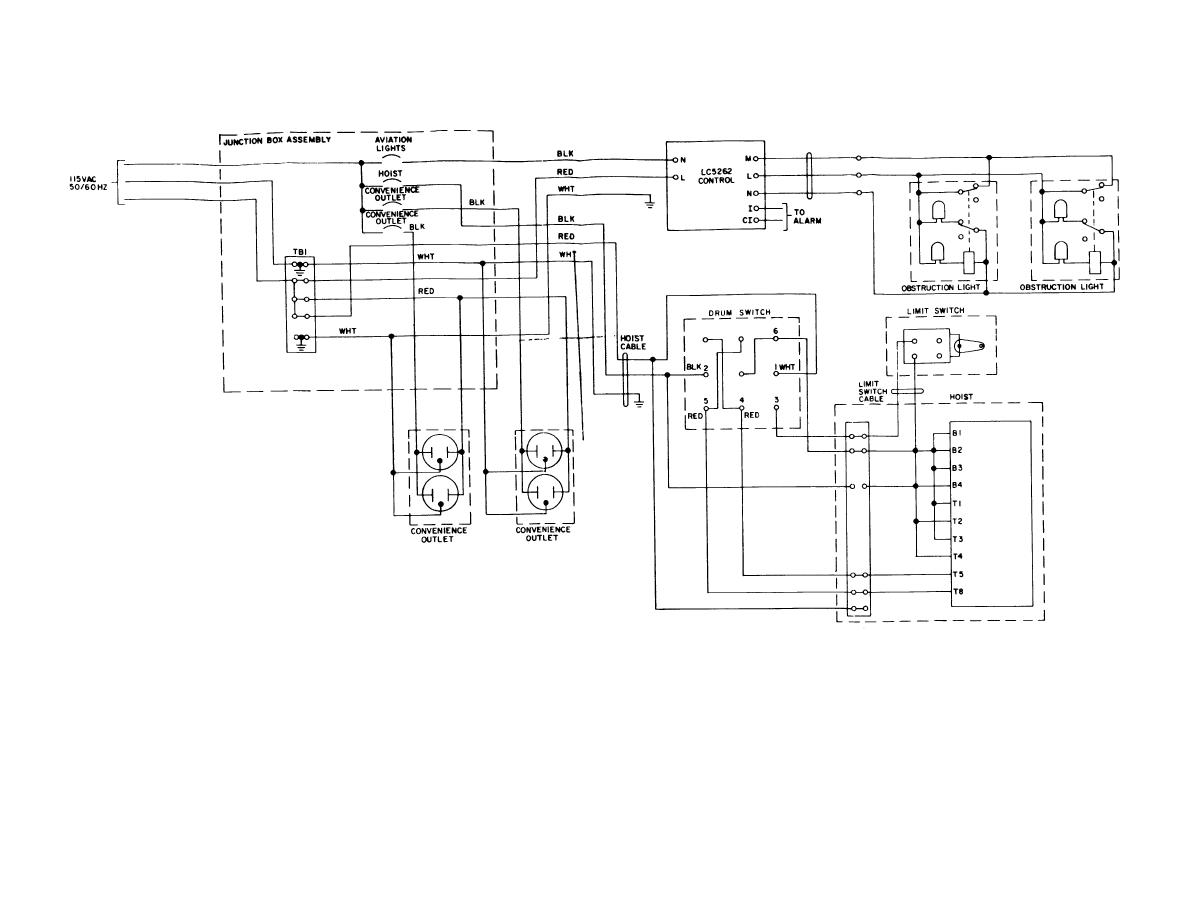
No description available.
Related Circuits
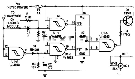
This circuit counts the flashes of turn signals. After approximately 70 flashes, a chime sounds to remind the driver to deactivate the turn signal. The period can be altered by using different taps on U2 if desired. BZ1 serves...
Instructions for constructing a circuit on veroboard by interpreting the schematic. Experienced constructors can directly reference the schematic to begin assembly, utilizing their knowledge of component placement and efficient use of veroboard space. Beginners should have certain foundational skills,...
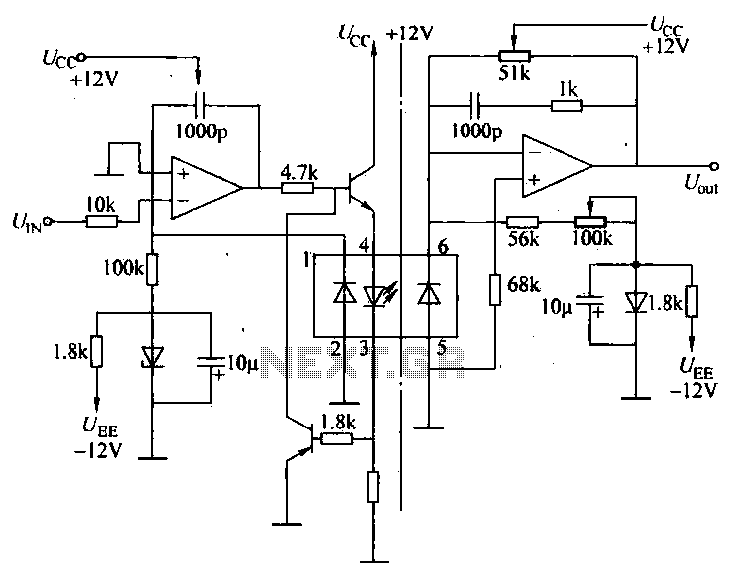
A universal optocoupler is utilized in electrocardiographs, as illustrated in Figure 5-29. Pin connections must be made carefully: the positive terminal should be connected to pin O, while the negative terminal should connect to the other pin. The control...
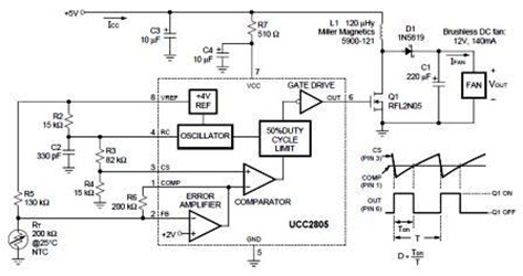
A temperature-controlled pulse-width-modulator (PWM) boost converter circuit diagram is illustrated in the following figure. This boost converter is designed to operate a 12V fan using a 5V supply while maintaining temperature control. The temperature-controlled PWM boost converter circuit operates by...
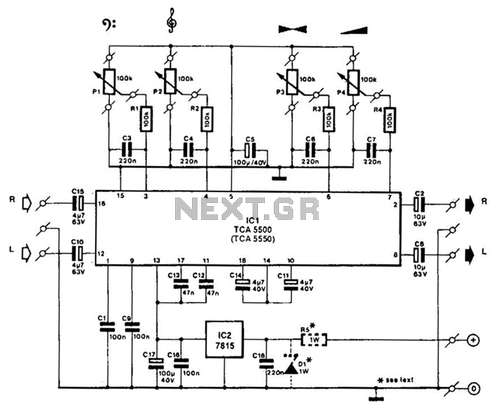
A Motorola TCA5500 or TCA5550 can be utilized to create a stereo preamplifier system equipped with tone controls. This circuit is designed to offer a gain of approximately 10 times, a tone-control range of 14 dB, and a volume...
An LED flasher circuit can be constructed using a 555 integrated circuit (IC). The use of the 555 IC allows for greater flexibility in adjusting the flashing rate of the LED. This LED flasher circuit is similar to other...