
Led Flasher Circuit Using 555 IC

The LED flasher circuit utilizing the 555 timer IC operates in astable mode, which allows it to continuously toggle the output state between high and low, thereby creating a flashing effect for the connected LED. The circuit typically consists of the 555 timer, resistors, capacitors, and the LED itself.
In this configuration, the frequency of the flashing can be adjusted by changing the values of the resistors (R1 and R2) and the capacitor (C1) connected to the 555 timer. The relationship governing the frequency (f) of the output signal can be expressed by the formula:
\[ f = \frac{1.44}{(R1 + 2R2) \cdot C1} \]
Where:
- R1 is the resistance connected between the discharge pin (Pin 7) and Vcc.
- R2 is the resistance connected between the discharge pin (Pin 7) and the threshold pin (Pin 6).
- C1 is the timing capacitor connected between the threshold pin (Pin 6) and ground.
The duty cycle, which determines the proportion of time the LED is on compared to off, can also be influenced by the resistor values. The duty cycle can be calculated using the formula:
\[ Duty Cycle = \frac{R2}{R1 + 2R2} \times 100\% \]
This allows designers to create various flashing patterns by selecting appropriate component values, making the circuit versatile for different applications such as visual alerts, decorative lighting, or signaling devices.
Power supply requirements for the circuit are typically modest, with the 555 timer functioning effectively within a voltage range of 4.5V to 15V. The LED should be connected in series with a current-limiting resistor to prevent damage due to excessive current. The choice of the resistor value will depend on the LED specifications and the supply voltage.
Overall, the 555 timer-based LED flasher circuit is a straightforward yet effective solution for generating flashing light effects, suitable for a variety of electronic projects.LED flasher circuit can be built based on 555 IC. Using 555 IC, the flashing rate can be more flexible to adjust. This LED flasher circuit is similar to our.. 🔗 External reference
Related Circuits

A 555 timer (IC1) generates a 120-Hz signal that is fed to a CD4013BE flip-flop (IC1-a), which divides the input frequency by two to generate a 60-Hz clocking frequency for the FET array (Q1 through Q6). Transformer T1 is...

The Switchgate is a simple dual gate circuit based on a 556 timer configured in monostable mode, featuring a trigger input that activates two switches. The outputs of the monostables are also available individually. Recent research has led to...
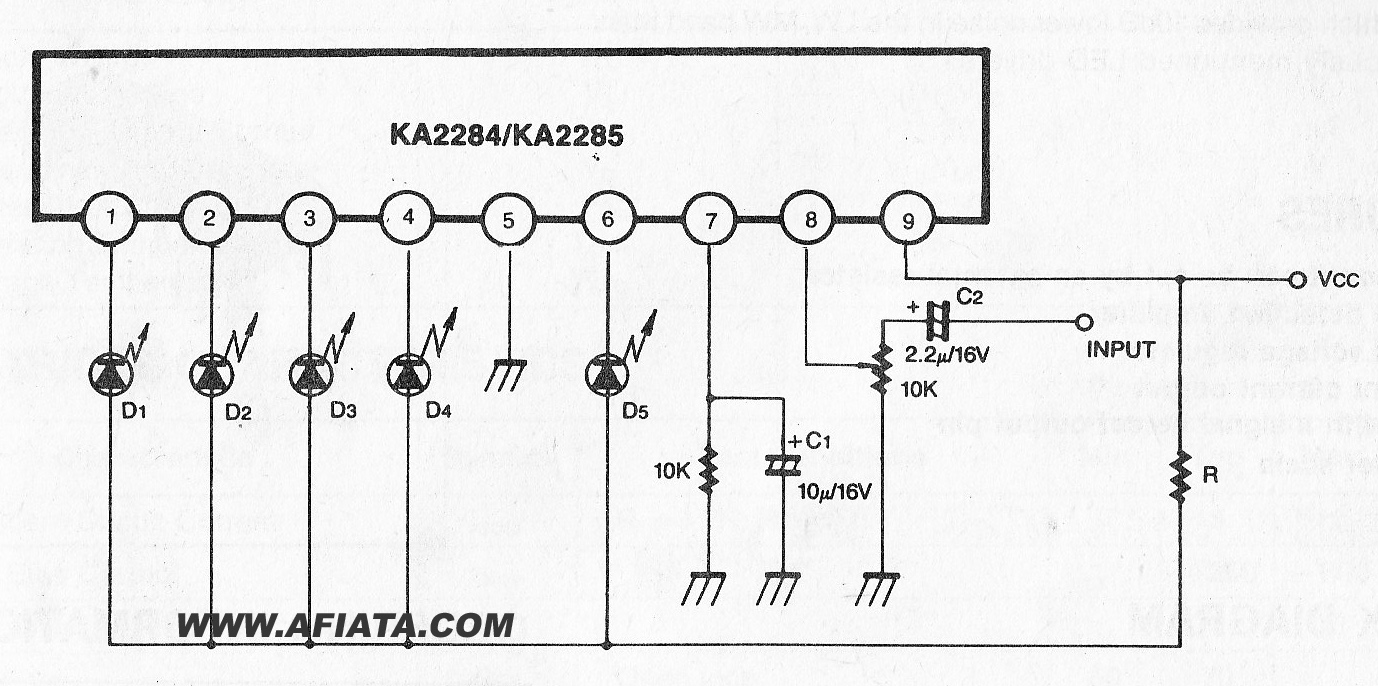
The KA2284 is a monolithic integrated circuit designed for 5-dot LED level meter drives with a built-in rectifying amplifier. It is suitable for both AC and DC level meters, such as VU meters or signal meters. The KA2284 integrated circuit...
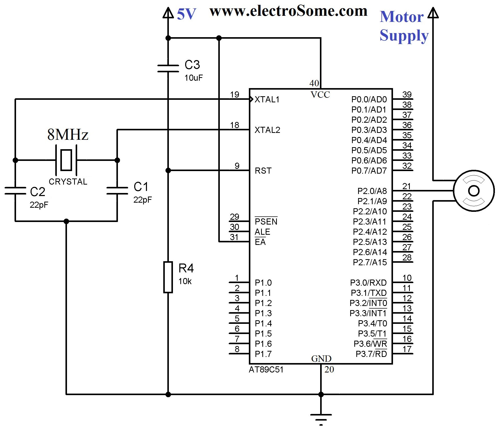
A servo motor employs a servo mechanism, which is a closed-loop system that utilizes position feedback to accurately control the angular position of its shaft. Stepper motors, which operate as an open-loop system, can also achieve precise angular control,...
The 555 timer is recognized as one of the most versatile and widely used integrated circuits globally. One of its potential applications is as a simple inverting Schmitt trigger. The 555 timer can be configured in various modes, including monostable,...
The section of the 1996 Ford Windstar wiring diagram includes details on power distribution, common connections, rear circuits, ignition systems, the fuse panel, battery connections, instrument illumination, radio wiring, left rear speaker connections, remote headphone module, solid-state components, and...