
Astable Multivibrator using NE 555 timer IC
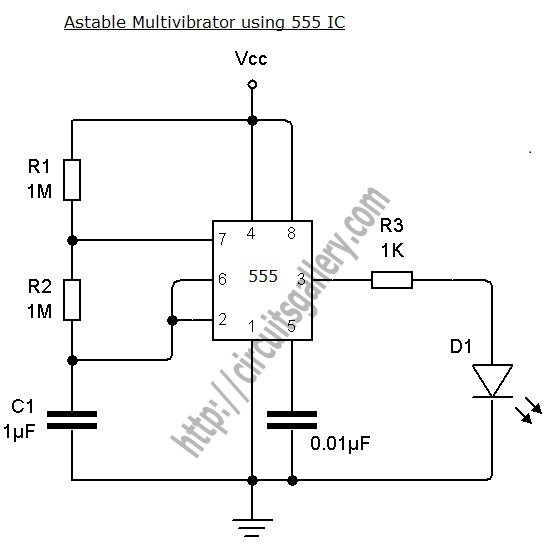
The astable multivibrator circuit based on the 555 timer operates in a continuous oscillation mode, generating a square wave output. The key components include two resistors (R1 and R2) and one capacitor (C1), which determine the frequency and duty cycle of the output waveform. The relationship between these components can be described using the formula for frequency:
\[ f = \frac{1.44}{(R1 + 2R2) \times C1} \]
This formula indicates that increasing the resistance values or the capacitance will decrease the frequency of oscillation. The duty cycle, which defines the proportion of time the output is high versus low, is influenced by the ratio of R1 to R2. For applications requiring specific duty cycles, careful selection of R1 and R2 is essential.
The 555 timer has two comparators internally that compare the voltage across the capacitor with predetermined threshold levels. When the voltage across C1 reaches 1/3 Vcc, the output of the lower comparator goes high, setting the flip-flop. Conversely, when the voltage reaches 2/3 Vcc, the upper comparator output goes high, resetting the flip-flop. This feedback mechanism ensures continuous oscillation.
The reset functionality provided by the fourth pin allows for external control of the timer operation. By applying a low signal to this pin, the timer can be effectively halted, which is useful for applications requiring synchronization or controlled timing sequences. The transistor Q2 acts as a switch, discharging the capacitor and ensuring the circuit can return to its initial state.
This astable multivibrator circuit is widely used in applications such as clock pulses generation, light flashers, tone generation, and frequency modulation. The simplicity of the 555 timer, combined with its versatility, makes it a popular choice for both educational purposes and practical electronic designs.Astable Multivibrator can be designed by using 555 timer IC, Op Amps and also using transistors. The 555 IC provide accurate time delay from mille seconds to hours. The frequency of oscillation can be controlled manually by simple modification. This is a simple 555 timer circuit project. Astable Multivibrator is simply an oscillator circuit that pr oduces continuous pulses. The frequency can be controlled by changing the values of R1, R2 and C1. When the capacitor voltage less than 1/3 Vcc, the lower comparator output will be high, then the control flip flop get set to High. (Q=1, Q`=0, Final output=1). 4th pin is Reset pin, a Low voltage at this pin resets the IC. The Low signal is applied to the base terminal of reset transistor Q2. Then it turns ON followed by Discharge capacitor Q1 and capacitor discharges. See the images below. 🔗 External reference
Related Circuits
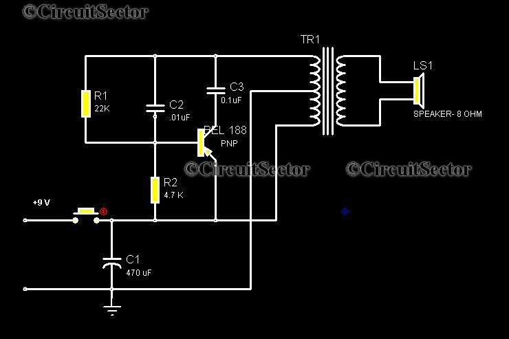
This circuit is a low-cost, one-touch doorbell using a Bel 188 transistor. It is likely one of the most economical bell circuits that can be constructed. The core component of this circuit is the output transformer from a push-pull...
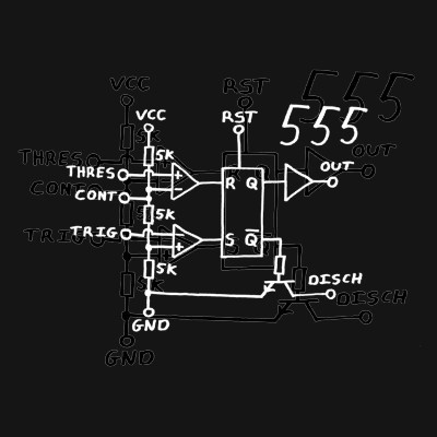
Classic 555 timer chip schematic circuit t-shirt by EEVblog picture on VisualizeUs - bookmark pictures and videos that inspire you. Social bookmarking of pictures and videos. Find your pictures and videos. The 555 timer IC is a versatile and widely...
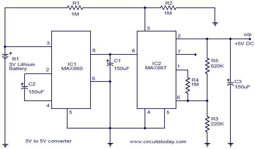
Voltage converter circuit diagram for converting 3 volts to 5 volts using CMOS monolithic ICs MAX660 and MAX667, which functions as a positive voltage regulator. The voltage converter circuit utilizes the MAX660 and MAX667 integrated circuits to step up a...
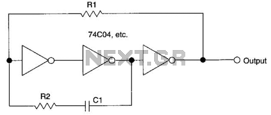
This circuit employs a protective resistor R2 along with a feedback resistor R1. Together, these components create a voltage divider that lowers the input voltage amplitude for IC1-a, ensuring that the protective diodes remain inactive. This arrangement enhances the...
This may appear to be a highly detailed post; however, it is being written to assist others who are experiencing a similar frustrating search for 12V timers that possess functionalities comparable to those found in mains timers. The intention...

The board can now be tested. Set the DIP switch to Switch1 ON, Switch2 OFF (15-second delay), Switch3 ON, and Switch4 OFF (4 rings to activate half for switching ON). To switch ON relay 1 (connected to RB0 of...